• The move to the new server is done. There are some software and database maintenance updates in process. This has us passing the hat around to help out. We appreciate any donations. Seriously, even a dollar helps. The payment page may be found here - https://www.audiokarma.org/support.html

Scott 299b OPT mystery

jaaronb

Active Member
Hey folks - I've got a great sounding Scott 299b that I picked up as a basket case a while back for about $60 from a guy a few towns over. It came to me with no knobs, no faceplate and most of the original tube component still installed. No real idea about it's background beyond that.

After a thorough restoration, it's a VERY strong performer (imo up there with the best tube gear available from any era). I love this amp.

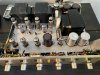
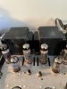
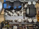
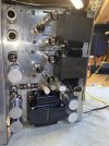
The weird thing is, this 299b is different from any other I've ever seen - it has the larger TRA 8-5-1 OPTs that were used in the 222c, 222d, LK-48 and LK-48b. This unit appears to be stock, but the chassis was clearly not designed to accommodate these OPTs - they nearly touch each other and make it impossible to access DC balance pots from the top of the chassis. As I said, the chassis doesn't *appear * to have been modified to fit these OPTs, but there's no way to be sure.

I assumed that perhaps mine was a late production run 299b, and maybe they used the 8-5-1 OPTs towards the end of the run, as an off the shelf OPT suitable for 7189 finals.

But I've never come across a photo or example of another 299b set up this way, so it's certainly possible someone shoehorned these OPTs in there are some point in the mists of the past. I'm sure others have done this in the past.

Love to hear from any Scott experts out there who can shed light on this or care to speculate.

Am I hearing something substantially different from what a non-chimera'd 299b sounds like? Is either OPT considered superior?

I'm also curious if these 8-5-1 OPTs would require any deviations in operating points from the standard 8-5 that shipped with the 299b.

Regardless, it sounds outstanding.


H.H. Scott OPT reference:
http://www.fmamradios.com/AmpSpecs.html

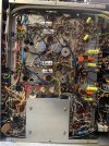
Proof of life:

8D27F2D0-9E03-4CBA-A807-0B295B158459.jpeg 25C47F4C-98EE-410B-8E70-F115D07B9939.jpeg D9F037F2-B344-463A-BF72-D7BADC6CC9C4.jpeg
 
Register to hide this ad
In my experience with the 299B, I have not seen one with the TR-8-5-1 output transformer. This looks like a post-refit with the 8-5-1 transformer. Looking at the circuits, not much different, but I'm wondering if the feedback network in your 299B was adjusted for the 222C transformer. They are different. The 222C also has a center speaker outlet with the 4 ohm tap at ground, while the 299B has the common (black) lead to ground without any center channel output.

(not an 'expert,' but I've seen a few Scotts)
 
Last edited:
In my experience with the 299B, I have not seen one with the TR-8-5-1 output transformer. This looks like a post-refit with the 8-5-1 transformer. Looking at the circuits, not much different, but I'm wondering if the feedback network in your 299B was adjusted for the 222C transformer. They are different. The 222C also has a center speaker outlet with the 4 ohm tap at ground, while the 299B has the common (black) lead to ground without any center channel output.
Far out. Do you know how the feedback network would need to have been altered to accommodate the 8-5-1 trafo?

I need to go through and thoroughly check and document all voltages.

I installed 10 ohm resistors from the finals' cathode to ground to make biasing easier, and have been able to set bias voltages on the nose at 25-26ma per tube.

It's been quite a while, but I believe voltages I have checked so far have been spot on.

The unit appeared to be all original when I got it - I don't think the previous owner had done anything with it.
 
Last edited:
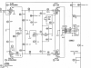
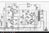
I can't tell you exactly how the negative feedback circuit should look like (that would take some design work), but I can show you from the schematics (available in the AK database) what they look like in the 222C (using the TR-8-5-1) and the 299B (using the TR-8-5). The component values of the feedback loop are highly dependent on the output transformer characteristics. The purpose of the negative feedback loop is to take a sample of the output voltage and 'feed it back' to the input of the driver out of phase to improve frequency response and greatly reduce distortion levels. The engineers took a little bit different approach between the two amps, as shown below. Best would be if you can look in your amp and see what components are actually present then we can judge what, if anything, needs to be done.


299B
The feedback network is the 15K resistor paralleled with the 120 mmf (pf) (R47 and C38) running from the 16 ohm output tap back to the cathode of V3 (the driver tube).

upload_2020-12-10_14-57-3.png

222C/LK48-B
The 222C/LK-48B feedback circuit is the 8.2K resistor paralleled with the 220pF cap (R43 and C28) from the 16 ohm output tap back to, again, the cathode of the V3-A driver tube. This network also has a 0.1uF cap in series with a 68 ohm 1W resistor (C29 and R49) also off the 16 ohm output tap to ground.

299C.jpg
 
But I've never come across a photo or example of another 299b set up this way, so it's certainly possible someone shoehorned these OPTs in there are some point in the mists of the past. I'm sure others have done this in the past.
Maybe somebody tried to hot rod it, or was trying to fix up a unit that had had the OPT’s robbed and either ordered the wrong ones or just used what was on hand?
 
can make it work, but the feedback stuff would need to be re-jiggered to make it all right. What parts are in yours?
 
I'm just about certain the parts on it are the stock 299b design. I will check as soon as I can get to it - hopefully tonight.

Could this presumed mismatch explain why, while the sonics are spectacular, the output seems lower than it ought to for an amp of its ~18 watt power rating? I'm running it into Altec 604-8gs, and have driven these 99db sensitive speakers with all manner of amps.

Part of what got me wondering about the suitability of the OPTs is that the amp doesn't seem to be delivering that kind of wattage.
 
Power testing it would be good if you have the gear. If the feedback is not right, it can reduce the overall gain of the amplifier. It can also lead to instability at the other extreme. No need to panic--sounds like it's working without histrionics as is, but would be good to understand how it's set up.
 
Was able to check this earlier, and it's got the stock 299b installed; 15k R47 resistor paralleled with the 220pF cap off the 16ohm output tap, running back to the v3 cathode.

So where do I go from here? Is it as simple as subbing in the 222c circuit as @Dave451 described above?

If so, would I then follow the 222c biasing procedure in terms of bias voltages?

I suspect it can't be that simple....
 
I think the resistor and cap values for the stuff going from the 16 ohm terminal back to the 6BL8 is going to be about right. The amount of voltage at the 16 ohm terminal of the 299b is double what the 222c would get because of where the ground connection is. Double the resistor and 1/2 the capacitor value would be an initial starting point, and the 299b values for those parts are pretty darn close. Its working into a lower value resistor too, so if anything you'll end up with a little less feedback on the 299b vs the 222c. Less feedback is less prone to stability issues, but measurable distortion goes up a bit.

where you'd probably need to change it, remove C71 (220pf) and replace it with an 0.1uf cap in series with a 68 ohm 1w resistor to ground. Possibly also need to change C36 from 470pf to 120pf, and R53 from 2.2k to 8.2k, though this one is a bit less critical. The 299b values are actually more aggressive so if anything they are rolling off more HF stuff than the 222c parts are.

really the right way to figure out what, if anything, needs to be done is to feed square waves into the power amp right at the top of the volume control and see what it looks like on the scope. If that looks right then you don't have to do anything.
 
I think the resistor and cap values for the stuff going from the 16 ohm terminal back to the 6BL8 is going to be about right. The amount of voltage at the 16 ohm terminal of the 299b is double what the 222c would get because of where the ground connection is. Double the resistor and 1/2 the capacitor value would be an initial starting point, and the 299b values for those parts are pretty darn close. Its working into a lower value resistor too, so if anything you'll end up with a little less feedback on the 299b vs the 222c. Less feedback is less prone to stability issues, but measurable distortion goes up a bit.

where you'd probably need to change it, remove C71 (220pf) and replace it with an 0.1uf cap in series with a 68 ohm 1w resistor to ground. Possibly also need to change C36 from 470pf to 120pf, and R53 from 2.2k to 8.2k, though this one is a bit less critical. The 299b values are actually more aggressive so if anything they are rolling off more HF stuff than the 222c parts are.

really the right way to figure out what, if anything, needs to be done is to feed square waves into the power amp right at the top of the volume control and see what it looks like on the scope. If that looks right then you don't have to do anything.

Thanks so much for these detailed suggestions.

I can make some of these revisions incrementally, or all at once without difficulty, but I unfortunately don't have a scope or signal generator.

Are there any other means to get an idea as to whether I should make any of these mods? Would we expect voltages to be off in particular sections?

Finally, if some or all of the mods were warranted, would I go about biasing the final tubes in the same manner as before?
 
a scope is really the only way to see whats going on with it. Voltages won't be affected, bias method is also the same as original.
 
Hello. Here it is 2023 and I am currently restoring a 299B with the same TRA 8-5-1 outputs installed. From what I can see they appeared to be original, no chassis mods to make them fit. I agree with Jaronb, even though I have more work to do on this amp it sounds absolutely GREAT! I will post additional information as I move forward.


PXL_20231113_010856924.jpg
 
Hello. Here it is 2023 and I am currently restoring a 299B with the same TRA 8-5-1 outputs installed. From what I can see they appeared to be original, no chassis mods to make them fit. I agree with Jaronb, even though I have more work to do on this amp it sounds absolutely GREAT! I will post additional information as I move forward.


View attachment 3034714
So prolly a late 299B factory modification. :idea:
 
It's a replacement. The originals were out of production and it's installed correctly. You may have to tweek the feedback. Otherwise a great looking unit and they do sound beautiful!
 
Just for grins, a short story on another modified 299B. I obtained one listed as "working fine" and in good physical condition from the ad pictures. Upon receiving it, though, I noticed something unusual about the output transformers: They were not stock 8-5 units, as in my other 299B, they were 8-5-4 transformers from the 7591 233 integrated amp! The leads were connected to the amp with wire nuts.

The transformers are considerably larger than the stock units and were actually resting on the DC balance controls--screws in one end only. The 8-5-4's have leads out of both sides of the bottom bell, instead of one side the 8-5. Soooo, some drilling was necessary to open up another hole for leads and to mount the larger units properly. As you can see in the pic, they barely fit. I also had to re-locate the DC balance controls (between the two middle 7189 tubes).

That done (and a re-cap), I did some measuring and found poor HF response, a crazy-looking 10 kHz square wave and doubtful stability. A good bit of work with the scope led to significant changes on the NFB network values and the step network in the PA driver (harking to the above posts), but this was successful and frequency response, THD+N, and power were all equal to or better than my stock 299B. 21W RMS per channel (despite more robust output transformers-30W per channel with 7591's). The square wave was tamed and the amp proved stable into capacitive-only loads.

The inboard output transformer was pretty close to the 5AR4 and chalkstick resistors, but operating temperatures were not much different from the stock 299B after extended operation.

After a bit of work, I ended up with a 'hybrid' 299B that sounds great (a little more low-end than stock) and should be reliable! Lesson: you never know what you're going to find when opening the box on a 'works fine' unit!

Dave
IMG_0864.jpg

IMG_0862.jpg
 
Just for grins, a short story on another modified 299B. I obtained one listed as "working fine" and in good physical condition from the ad pictures. Upon receiving it, though, I noticed something unusual about the output transformers: They were not stock 8-5 units, as in my other 299B, they were 8-5-4 transformers from the 7591 233 integrated amp! The leads were connected to the amp with wire nuts.

The transformers are considerably larger than the stock units and were actually resting on the DC balance controls--screws in one end only. The 8-5-4's have leads out of both sides of the bottom bell, instead of one side the 8-5. Soooo, some drilling was necessary to open up another hole for leads and to mount the larger units properly. As you can see in the pic, they barely fit. I also had to re-locate the DC balance controls (between the two middle 7189 tubes).

That done (and a re-cap), I did some measuring and found poor HF response, a crazy-looking 10 kHz square wave and doubtful stability. A good bit of work with the scope led to significant changes on the NFB network values and the step network in the PA driver (harking to the above posts), but this was successful and frequency response, THD+N, and power were all equal to or better than my stock 299B. 21W RMS per channel (despite more robust output transformers-30W per channel with 7591's). The square wave was tamed and the amp proved stable into capacitive-only loads.

The inboard output transformer was pretty close to the 5AR4 and chalkstick resistors, but operating temperatures were not much different from the stock 299B after extended operation.

After a bit of work, I ended up with a 'hybrid' 299B that sounds great (a little more low-end than stock) and should be reliable! Lesson: you never know what you're going to find when opening the box on a 'works fine' unit!

Dave
Very interesting. I wonder if this was a late-model factory option? Seems to be several in this thread.

Always good to have bigger iron in this era tube amps. As long as they fit the electrical parameters. And the chassis! :)
 
Interesting thought indeed, but clearly this one wasn't a factory mod! In fact, the 8-5-4 transformers have around 7K ohms primary impedance, compared to around 6K for the 8-5's, hence the need for re-configuring the NFB and step network values. I corresponded with one of our top experts on negative feedback, Dave Gillespie, and his thought was that the 8-5-4's were going to be better quality iron than any new production off-shelf replacements I could find, at the expense of a little tuning. So, that's what I did (cheaper, too!).

It's maybe worthwhile noting that Dave G did a masterful job of adapting 7591 output transformers (from the Heath AA-100) to EL84/7189 operating in his Fisher SA-100 clone. Worked for this 299B well enough!
Dave
 
Interesting thought indeed, but clearly this one wasn't a factory mod! In fact, the 8-5-4 transformers have around 7K ohms primary impedance, compared to around 6K for the 8-5's, hence the need for re-configuring the NFB and step network values. I corresponded with one of our top experts on negative feedback, Dave Gillespie, and his thought was that the 8-5-4's were going to be better quality iron than any new production off-shelf replacements I could find, at the expense of a little tuning. So, that's what I did (cheaper, too!).

It's maybe worthwhile noting that Dave G did a masterful job of adapting 7591 output transformers (from the Heath AA-100) to EL84/7189 operating in his Fisher SA-100 clone. Worked for this 299B well enough!
Dave
MAN! But those big 8-5-4 transformers look so yummy!
 
Back
Top Bottom