• The move to the new server is done. There are some software and database maintenance updates in process. This has us passing the hat around to help out. We appreciate any donations. Seriously, even a dollar helps. The payment page may be found here - https://www.audiokarma.org/support.html

Scott 299b Restoration

bberkom

AK Subscriber
Subscriber
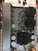
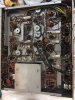
I just had one of those days I dream about for stereo gear. I lucked into a big stash of nice tube gear being sold by a widow, whose husband collected all kinds of tube gear. I picked up this 299b and a Dynaco PAS2 preamp today, and I am probably going back tomorrow for an ST-70. I ran out of money and wanted to be able to offer something fair since she has no idea how to sell the stuff. I am planning to help her price and sell the stuff on craigslist, but for now, I need to restore this Scott!

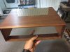
I brought it up slowly, and low and behold, it is fully functional with no issues to speak of besides a couple of scratchy controls. I'll have to say, it sounded quite good for the couple of minutes I listened to it. The faceplate is in great shape outside of some of the lettering missing around the volume control. It also came with wood case that is in very good shape, but I removed it before I remembered to take pictures. Preamp tubes are all 12AX7 RCA's, 6BL8 tubes are original Scotts, but output tubes are not 7189's. They are General Electric 6BQ5/EL84's. So I think I need to get the correct 7189 output tubes based on what I have read, but some guidance there would be helpful.

I know a new rectifier, coupling caps, and cans/electrolytics are all needed. I've read about recommended ways to replace the can capacitors and any other threads I could find on this unit. Other advice on this restoration as I start to compile a parts lists would be great, and I am sure I will run into some issues along the way.
 

Attachments

  • IMG_6249.JPG
    IMG_6249.JPG
    72.4 KB · Views: 147
  • IMG_6251.JPG
    IMG_6251.JPG
    51.2 KB · Views: 135
  • IMG_6253.JPG
    IMG_6253.JPG
    92.6 KB · Views: 143
  • IMG_6254.JPG
    IMG_6254.JPG
    86.8 KB · Views: 129
Register to hide this ad
Great looking 299B! You've got all the main things listed, I think. Sovtek EL84M's are a great choice for output tubes. Used them for both 299b's I've done.

Increase the value of the first dropping resistor in the bias supply when you replace the selenium bridge rectifier. The output voltage will be higher with the Silicon unit. About 30 ohms at 3-4 watts should do it. Check the resistors in the bias supply string; mine had all drifted high.

Consider replacing or bypassing the two 0.0012 uF couplers early in the audio path . Dave G says these are part of the LF rumble filter no longer needed. One of mine had ceramics and the other Pyramids. I replaced the Pyramids and it opened the amp up significantly. Yours appear to be ceramics and are near those 0.1 uF white caps going toward the front panel.

Consider adding 100 ohm screen protection resistors to protect the output tubes and 10 ohm cathode resistors to set bias on each output tube. By all means, add a CL-80 for inrush current reduction. Keep us updated on your Progress!

Congrats on the find!
Dave
 
Great looking 299B! You've got all the main things listed, I think. Sovtek EL84M's are a great choice for output tubes. Used them for both 299b's I've done.

Increase the value of the first dropping resistor in the bias supply when you replace the selenium bridge rectifier. The output voltage will be higher with the Silicon unit. About 30 ohms at 3-4 watts should do it. Check the resistors in the bias supply string; mine had all drifted high.

Consider replacing or bypassing the two 0.0012 uF couplers early in the audio path . Dave G says these are part of the LF rumble filter no longer needed. One of mine had ceramics and the other Pyramids. I replaced the Pyramids and it opened the amp up significantly. Yours appear to be ceramics and are near those 0.1 uF white caps going toward the front panel.

Consider adding 100 ohm screen protection resistors to protect the output tubes and 10 ohm cathode resistors to set bias on each output tube. By all means, add a CL-80 for inrush current reduction. Keep us updated on your Progress!

Congrats on the find!
Dave
Thanks for all of the information. I am going to work on my parts list tomorrow and I'm sure I'll have some questions!
 
Some vintage units have been used regularly and the power supply caps will still be ok. In fact, if you are just thinking of keeping the unit in its most collectible condition, then leaving the unit unrebuilt is the best course. I have some Scotts and EICO units like that. Of course i don't use them, except maybe twice a year i will hook them up to the variac and do a slow voltage start. An easy way to check if the power supply caps need replacing is to carefully, check the temp of the can cap after say 10 to 30 minutes of operation. If the can is noticeably warm or worse hot then you need to replace as that means the cap is going bad. If the can cap is close to the 5ar4 rectifier or power tubes that will make a difference. In lieu of a total rebuild at this time you can devote your efforts to checking parts values in critical areas like the plate and cathode resistors of the small tubes. Those carbon comp resistors may have drifted off spec by now. Unless the resistor is grounded you will have to "lift a leg" or one of the connections to make an accurate reading of a resistor in circuit. sometimes it is just easier to replace the part instead or going thru all the trouble. If you go that route of just replacing the original resistors the 1/2 watt 1% metal film resistors are good. It is best to rebuild one channel at a time and check your work after you finished rebuilding a section by turning on the amp and checking the sound of the newly rebuilt channel. good luck
 
Last edited:
I just completed a Scott 299b restoration and there is plenty of room under the hood for replacement lytics., if you don't want to mess with restuffing all the cans. Send me your email address and I'll send along some high res shots.
A great amp, congratulations!
 
Some vintage units have been used regularly and the power supply caps will still be ok. In fact, if you are just thinking of keeping the unit in its most collectible condition, then leaving the unit unrebuilt is the best course. I have some Scotts and EICO units like that. Of course i don't use them, except maybe twice a year i will hook them up to the variac and do a slow voltage start. An easy way to check if the power supply caps need replacing is to carefully, check the temp of the can cap after say 10 to 30 minutes of operation. If the can is noticeably warm or worse hot then you need to replace as that means the cap is going bad. If the can cap is close to the 5ar4 rectifier or power tubes that will make a difference. In lieu of a total rebuild at this time you can devote your efforts to checking parts values in critical areas like the plate and cathode resistors of the small tubes. Those carbon comp resistors may have drifted off spec by now. Unless the resistor is grounded you will have to "lift a leg" or one of the connections to make an accurate reading of a resistor in circuit. sometimes it is just easier to replace the part instead or going thru all the trouble. If you go that route of just replacing the original resistors the 1/2 watt 1% metal film resistors are good. It is best to rebuild one channel at a time and check your work after you finished rebuilding a section by turning on the amp and checking the sound of the newly rebuilt channel. good luck

Thanks for the advice. I probably will go ahead with a restore since I plan to use the heck out of this thing once it's ready. I'll be checking resistor values as I go and may end up replacing some, but I'm going to try to leave as many of the originals in there as I can for now.
 
I just completed a Scott 299b restoration and there is plenty of room under the hood for replacement lytics., if you don't want to mess with restuffing all the cans. Send me your email address and I'll send along some high res shots.
A great amp, congratulations!
PM incoming, that would be super helpful! I was planning to get them in the chassis instead of stuffing the cans.
 
Great looking 299B! You've got all the main things listed, I think. Sovtek EL84M's are a great choice for output tubes. Used them for both 299b's I've done.

Increase the value of the first dropping resistor in the bias supply when you replace the selenium bridge rectifier. The output voltage will be higher with the Silicon unit. About 30 ohms at 3-4 watts should do it. Check the resistors in the bias supply string; mine had all drifted high.

Consider replacing or bypassing the two 0.0012 uF couplers early in the audio path . Dave G says these are part of the LF rumble filter no longer needed. One of mine had ceramics and the other Pyramids. I replaced the Pyramids and it opened the amp up significantly. Yours appear to be ceramics and are near those 0.1 uF white caps going toward the front panel.

Consider adding 100 ohm screen protection resistors to protect the output tubes and 10 ohm cathode resistors to set bias on each output tube. By all means, add a CL-80 for inrush current reduction. Keep us updated on your Progress!

Congrats on the find!
Dave
Want to make sure I have a couple of things straight as I compile my parts list. Looking at the amp and the schematic, the dropping resistor you recommend replacing in the bias supply after the rectifier is R126, the 10ohm 2w resistor, correct? I also found the two .0012 ceramics you mentioned and will replace those with films. I am going to order 1/4w 10ohm cathode resistors and 1/2w 100 ohm screen protection resistors for the output tubes. I will need some guidance making sure I add those in the correct locations, but lots of work to do before then!

I have a couple of CL-80's on hand already. I plan to install in between the fuse holder and the PT. Seems like a good place for it, but let me know if you think there is a better place for it in this particular amp. Thanks again.
 
Thanks a ton. I'll look for them later today. Very excited about getting into this thing!
 
Hey Diverted,
I also have an unrestored 299b and would like to see your pictures if you don't mind.
Thanks,
John
 
bberkom,
Yes, the 10 ohm 2W resistor is the one to replace (use 4W). The 18 ohms in the bias supply are the ones to check for drift, but you may want to also check the other dropping resistors in the B+ supply chain as well. As for the CL-80, you want to get it in the power transformer primary loop. Anywhere in there will work. Make sure you put it in a place where you can keep it away from other components, as it generates a fair amount of heat during operation by its' nature. I did not do screen and cathode resistors for this one, but we can walk through that. 1/2 w for screen and 1/4w for cathode resistors are the usual values.

Here's a line to the last 299B restore I did that may prove helpful: http://audiokarma.org/forums/index.php?threads/scott-299b-restore.721347/

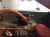
Post 19 shows the CL-80. The leads are stiff, so I connected it as shown. Others may want to add a tie strip, but there's little room to work in that area of the chassis.

Dave
 
bberkom,
Yes, the 10 ohm 2W resistor is the one to replace (use 4W). The 18 ohms in the bias supply are the ones to check for drift, but you may want to also check the other dropping resistors in the B+ supply chain as well. As for the CL-80, you want to get it in the power transformer primary loop. Anywhere in there will work. Make sure you put it in a place where you can keep it away from other components, as it generates a fair amount of heat during operation by its' nature. I did not do screen and cathode resistors for this one, but we can walk through that. 1/2 w for screen and 1/4w for cathode resistors are the usual values.

Here's a line to the last 299B restore I did that may prove helpful: http://audiokarma.org/forums/index.php?threads/scott-299b-restore.721347/

Post 19 shows the CL-80. The leads are stiff, so I connected it as shown. Others may want to add a tie strip, but there's little room to work in that area of the chassis.

Dave
Thanks again. Very helpful. I'll hopefully be placing my parts order today or tomorrow. For the replacement electrolytics for the can caps, is it easier to work with and fit axial or radial leads? I am planning to just buy some good nichicon or panasonic replacements for under the chassis. I also see the one 30/20uf can are wired in parallel, so I'll probably just grab a single 50uf cap for that one.
 
I usually work with axials (i.e. the bias supply replacements in my thread) if they will fit. Lead treatment on radials looks odd to me if there's a gap between connections, but on some installs they work perfectly, particularly if you put in a tie strip underneath a can you're leaving in place and connect several radials to it. So, I guess my brilliant answer is: it depends! I usually buy Nichicon, but Panasonics will work fine. Get 105 degrees centigrade rating if they have them in your size, but 85's will still work ok. The 299B is a hot runner (don't be surprised when you get it going!). Single 50 uF is great with the proper voltage rating. When I was mixing and matching on my rehabs, I had 30 uF and 20 uF sections available, so I paralleled them. Be sensitive to how things are grounded and try to use the same ground points to avoid any hum from inadvertent ground loops.

One thought on can capacitor aesthetics: Some folks want to leave the original cans above chassis for the look and install under chassis, or even re-stuff the originals. I actually like the look of the black JJ cans and used them in both my 299B restores and that saved me from a lot of under-chassis work with axials or radials. There's not a great deal of room under the 299B chassis. In the linked install, I actually epoxied the JJ's to the original can wafers and really liked how that turned out. Like you, I intended to use the amp a lot and it was going to be in a cabinet anyway. Also, the JJ's are quite economical compared to buying AE aluminum units or, say, Hayseed Hamfest custom aluminum cans (say, 35 to 40 dollars each for multi-sections!). As always, a matter of personal preference, but it's nice to have options.
Dave
 
I see. So you replaced the the 20/20/25/25 can with a 32/32 JJ for the 20uf sections and then added the two 25uf under the chassis to complete that replacement. But you went with under the chassis caps for the 100/100/10 can replacements which look like they fit well.

For the 30/20 caps, I don't see any cans with the same specs, but it looks like you used JJ's there as well. Did you stick with the 32/32's for those or did you find a JJ that was a 30/20?

Again, thanks for the help. I want to have a good plan of action before I dive in, so trying to consider all of my options.
 
Went back to my notes. Used a JJ 50 + 50 two section (one side only) to replace C1; a 32 + 32 two-section to replace C2 and another 32/32 to replace the 20 uF HV sections of C3 (C3 A and B). The JJ's are all rated at 500VDC. You can easily use a little more capacitance down the power supply string for C2 and C3, but you want to avoid a lot more capacitance for the initial filter cap, C1, when you have a tube rectifier, so I stayed at 50 uF for the combined C1A and C1B values (which, as you note, are wired in parallel anyway).

The Antique Electronic Supply/Tube Depot catalogue numbers are CP-JJ-32X2-500V ($8.50ea) and CP-JJ-50X2-500V ($8.95).

As you noted, I used 25 uF axials (Sprague Atoms, 25 uF, 25VDC) for the cathode bypass caps in V2 and V7 (C3 C & D) (AES/Tube Depot cat number CP-AT-25-25V at $2.45 ea).

And, yes, I went with under chassis for the bias supply caps (AES/Tube Depot F&T caps, cat number CP-FT-100-100V, $2.45 each) and a 10 uF axial for C7.

Hope this helps!
Dave
 
You are the man! It's a very clean way of dealing with all those cans. I'll have a look and keep things updated once my parts get in. I picked up a PAS2 and an ST-70 in the same haul that I'm trying to order parts for too, so I'm up to my ears in lists and projects right now!
 
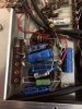
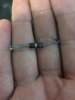
I got my parts in and spent some time today rebuilding the bias supply. I also went ahead and replaced the rectifier with a fairchild GBU4G. The 18ohm resistors in the bias string measured a tad high, and I had already ordered some wirewound replacements in case they were needed, so I went ahead and put the new ones in along with the larger initial 30 ohm dropping resistor. I need to go get some mounting screws for the rectifier and for the terminal strip (I'm going to add like you did so the connections for the 10uf cap to the bias supply aren't just floating). The 10mfd replacement section for C6 and R122 are all I have left to replace before I am done with the bias section. I think I got everything right, but I am going to wait until I have everything in place before I fire it up.

However, I have one question. R122 is spec'd in the schematic as 8.2K, but the resistor I pulled out is marked as a 6.8K and measures right at 6.8K. Should I just stick with the 6.8K or do I need to change to the 8.2K in the schematic?
 

Attachments

  • IMG_6322.JPG
    IMG_6322.JPG
    67 KB · Views: 60
  • IMG_6321.JPG
    IMG_6321.JPG
    36.4 KB · Views: 57
  • IMG_6323.JPG
    IMG_6323.JPG
    65.2 KB · Views: 57
Looking Good! Can't tell from pictures, but be sure your bias supply electrolytics have their + sides to chassis ground. Not sure about the 6.8 k resistor. Mine was 8.2 k in both units. Did the 6.8k look Original? Seems like that would make the -25 v supply run high. As always, the proof is in the measuring. Final checks should be with the 12AX7 tunes installed.
 
I went ahead and put the original 6.8K resistor in for the -25v supply and brought it up. Everything seems to be running fine, however, my voltages are still a few volts high compared with the schematic. I replaced the rectifier and used a 30ohm resistor in place of the 10ohm for R126. Of course I'm at 124VAC at the wall in my house! I don't have a variac handy to set voltages running at 117VAC. Are the below voltages concerning, or am I in the ballpark? These are taken with only 12AX7's installed.

Schematic: -53; -51; -48; -46; -25
Actual: -57; -55; -52; -50; -27.5
 
Back
Top Bottom