• The move to the new server is done. There are some software and database maintenance updates in process. This has us passing the hat around to help out. We appreciate any donations. Seriously, even a dollar helps. The payment page may be found here - https://www.audiokarma.org/support.html

Scott LK-48B

knockbill

Lunatic Member
I started to dig into the Scott LK-48B I got at K'town last week,, and want to replace the Selenium bridge and dropping resistor for it,,, I have the kit build manual and a schem for it but the value for the Se rectifier isn't listed in the parts list or schem I have.. Just need to know value of Si bridge or dropping resistor for it... Schem I have says output of bridge needs to be -55VDC
TIA
 
Register to hide this ad
In restoring my LK-48B, I used a commonly available 3A 400PIV rated silicon bridge rectifier and replaced the 10 ohm R210 first-in-line dropping resistor with a 30 ohm 3W resistor.
 
I found a British forum that used a 4A/200V bridge and 22R resistor... I I have a 4A/400V bridge,, and 22 to 30R sounds like it will be good,,, I'll adjust it when get to bias/heaters...
Thanks for the input!
 
thats running either a 150mA or 300mA heater string plus a pinch more for the bias pots. The bridge isn't very critical honestly, whatever you can get easily will do it.
 
What they all said. I use a square block type. You can bend the four leads into a loop. You can also attach it with a screw in one of the original selenium bridge attachment holes. Not a lot of current, not a lot of voltage.

Something like this. Bridge.jpg
 
Yep,,, That was my first choice...but I only had teh kind with 4 wires sticking out one end, so used that for now,, I'll put in one with teh hole and lugs when I find one,,, I think it will look neater...
Just trying to see if I could get bias ckt fired up, and it works fine,,,
Thanks for the input!!!
 
Last edited:
Yep,,, That was my first choice...but I only had teh kind with 4 wires sticking out one end, so used that for now,, I'll put in one with teh hole and lugs when I find one,,, I think it will look neater...
Just trying to see if I could get bias ckt fired up, and it works fine,,,
Thanks for the input!!!
Yes, nothing wrong with that! Please, keep us posted with pictures. If I can help, please let me know. I have had/have most of the Scott tube amps.
 
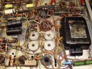
Here's a pic of how I found it,, I had the knobs,, it literally had my name on it, so I had to grab it!! It has mismatched OPTs, but I think I have a plan to get around that... I think someone tried to recap it a while ago, and had some problems,, a lot of coupling caps were replaced but not very recently... there were few broken tag strips I replaced, along with missing Loudness pot, and broken AC receptacles in the back,,, I replaced the switched one and put teh AC power switch where the unswitched rec was... The 55V PT winding was disconnected from teh ckt, and I worked on that today... Also got comparable loudness pot partially wired, but teh schem I have isn't exactly like my chassis so I'll have to make a few changes,,,
That's as far as I got with it so far!
 

Attachments

  • P4160045.JPG
    P4160045.JPG
    90.3 KB · Views: 77
HA,,,,
trying to get teh missing Loudness pot I replaced wired in,,,
I have a copy of the kit assembly manual and a schematic,,, but neither one are a match for my amp! Its expected that designers make changes without issuing updated schems , but these aren't even close!
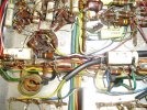
First,, I'm not sure where the white and yellow wires go,, they come from teh Treble pot (far right) and look reach the Loudness pot, (far Left) of pic)...

2ND teh two cement resistors on teh speaker switch, above R side pot are caps in my manual,,, one has a wire off, but it probably goes where it reaches, just above the other one,,
Only clue I have is teh loudness pot was the only thing completely missing ,,,,, so far!!!
Guesses and hints are welcome!!!
TIA
 

Attachments

  • P4260046.JPG
    P4260046.JPG
    135.8 KB · Views: 22
Last edited:
one thing with kit stuff, you can't guarantee it was built right to begin with, or that someone hasn't messed with it at some point over the last 60-some years. Worst case, go by the assembly manual if the connections as-found just don't make any sense.
 
That's true, I had a WA-P2 preamp that had a pinched wire in it,, and it provided a quasi ground to a miswired ckt, that thing could have never worked... Took a while but I found it!!!,,,
The schem I have is a closer match than teh DIY manual I copied,,,, and least teh schem shows caps where caps are, and not resistors!!!! Also,, I kinda doubt the guy that built it would have changed parts that weren't in teh kit, but who knows,,, I'm really not sure the original builder ever got it running as at least half of parts I came in contact with had a cold solder joint on one end,,, Then it went on to someone that replaced a bunch of film caps, but that was a while ago also,,,
It also had a pair of diodes in the 5AR4 socket, that were baked,,, and the first B+ dropping resistor was blown in half,,, I'm calling it a victory that all teh windings are intact and at the proper V!!!!
Now I gotta start thinking about the OPT mismatch,,,, maybe I could swap the Fisher pair for one good Scott OPT,,,, rather than cobble the pair of Fishers in it...
Fun ain't it!!!!

 
Last edited:
Back to the Scott,,, There is a can cap in this guy that has two 22/450s in parallel,,, that some one already replaced with a pair of 22/450 separate caps on long leads and just laying on the chassis,,, I think I can do better than that,, Question is, can I just use one 47/450 cap and mount it closer to the resistor that feeds it as there is room for one cap there but two wont fit,,, Then I can just run the grd wire back to the original can,,,
That will allow the chassis to lie flat without a hot cap making a see/saw outta it!!!
I saw a guy on a video move the pair over to where I want, but he obviously had those long skinny caps,,, Red wire from new cap to Resistior that feeds it,,, not connected yet,,
Pic of what I got now, top Left and where I want to mount new 47/450 bottom Right, next to PT
TIA
 

Attachments

  • P5030050.JPG
    P5030050.JPG
    196.6 KB · Views: 36
Last edited:
I've subbed single caps for parallel more than once. I figured they probably did the parallel thing to use parts already in inventory or something.
 
That's what I figured also,,, and the fact that bigger sizes cost more back then,, I wish this thing still had some of the chassis lettering still on it,,,
 
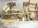
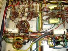
Todays project is to try and get OPTs wired to the proper speaker strips in the back of the amp,,, The OPT in the pics is the original one, Right OPT is a Jap one, that I cant find any wiring diagram for ,,,
The secondary's coming out of teh original (L) one is wired to the T strip in front of it, but the Black lead from strip to the rear screw strip is cut at the tag strip,,, The other OPT has different color wires and the tag strip has different components on it also,,
My biggest hurdle is the Manual and schem I have are for a LK48 B which is laid out and wired different than my amp!! I guess Scott built more than on style and gave em both the the sam model number...
Posting pics as I was asked to earlier in this thread...
Gotta watch what you're wishing for,,, this one is a mess!!

Info on replaced OPT,,, Instant HiFi OPT,, Osaka Koha Co Lmt,,Japan # OT-5A 25W
TIA
 

Attachments

  • P5040050.JPG
    P5040050.JPG
    182.6 KB · Views: 17
  • P5040050.JPG
    P5040050.JPG
    177.2 KB · Views: 21
Back
Top Bottom