• The move to the new server is done. There are some software and database maintenance updates in process. This has us passing the hat around to help out. We appreciate any donations. Seriously, even a dollar helps. The payment page may be found here - https://www.audiokarma.org/support.html

SE to PP linestage

PakProtector

AK member
I want to try another PP output linestage. I have one that runs a LTP of EL84 and don't quite feel like duplicating it. Sooooo....

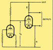
12B4 SE amplifier, LED biased and resistive loaded, followed by another 12B4. Maybe followed by a 12A4...

B+ around 400V, 15000 Ohm plate load on the main amplifier, and 10kOhm plate and cathode loads. Plate voltage on the amplifier stage about 120V. Big coupling caps( motor runs, 370 VAC/5 uF most likely.

Thanks to REALLY poor PSRR, the B+ is going to need some competent filtering.

It ought to be fun... :) It will need to drive a digital cross over.

Douglas
 
Register to hide this ad
I want to try another PP output linestage. I have one that runs a LTP of EL84 and don't quite feel like duplicating it. Sooooo....

12B4 SE amplifier, LED biased and resistive loaded, followed by another 12B4. Maybe followed by a 12A4...

B+ around 400V, 15000 Ohm plate load on the main amplifier, and 10kOhm plate and cathode loads. Plate voltage on the amplifier stage about 120V. Big coupling caps( motor runs, 370 VAC/5 uF most likely.

Thanks to REALLY poor PSRR, the B+ is going to need some competent filtering.

It ought to be fun... :) It will need to drive a digital cross over.

Douglas
Why not use a 12AU7 or 6SN7? Back in the late 1950s, Ampex made the 351 tape electronics (on which most of the RCA Living Stereo catalog was recorded). Those electronics had a push pull output using a 12AU7. They had no problem putting out +24dBm. 0dBm is 1 mW into 600 Ohms BTW, which is plenty of Voltage to drive most amps.

The output transformer for a 12AU7 or similar tube (6SN7, 6CG7) would be a lot easier to build than one for a power tube- you'd get wider bandwidth and lower distortion.

If you used a 12AT7 as the output tube, driving a PP output transformer, using a Constant Current Source in the cathode circuit you'd have enough gain that you might not need another tube in the line stage and it would be able to handle a single-ended or balanced input. I used exactly this sort of circuit in a microphone preamp I recently built. It makes +24dBM at clipping, about 32V. Output transformers for this application would be easy to find.
 
Why not use a 12AU7 or 6SN7? Back in the late 1950s, Ampex made the 351 tape electronics (on which most of the RCA Living Stereo catalog was recorded). Those electronics had a push pull output using a 12AU7. They had no problem putting out +24dBm. 0dBm is 1 mW into 600 Ohms BTW, which is plenty of Voltage to drive most amps.
interesting. have a pair of ampex 351 modded as standalone mic preamp. i have not looked at the circuit.
 
I want to try another PP output linestage. I have one that runs a LTP of EL84 and don't quite feel like duplicating it. Sooooo....

12B4 SE amplifier, LED biased and resistive loaded, followed by another 12B4. Maybe followed by a 12A4...

B+ around 400V, 15000 Ohm plate load on the main amplifier, and 10kOhm plate and cathode loads. Plate voltage on the amplifier stage about 120V. Big coupling caps( motor runs, 370 VAC/5 uF most likely.

Thanks to REALLY poor PSRR, the B+ is going to need some competent filtering.

It ought to be fun... :) It will need to drive a digital cross over.

Douglas

Also, have you ever explored the possibility of a bipolar supply?
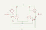
I'm assuming you want to go unbalanced to balanced signal. How about a DC coupled common cathode to cathodyne?
B+ around 400V on a 12B4? I would make sure to reference the heater 50% of B+ since those do have a 200V cathode to heater limit.
Screenshot from 2026-09-03 09-14-21.png

Most low PSRR issues can be resolved.It just take time with signal analysis to find out what method of noise cancellation works. So you don't necessarily need to build a virtual battery to make a low noise circuit.
 
Last edited:
Also, have you ever explored the possibility of a bipolar supply?
I'm assuming you want to go unbalanced to balanced signal. How about a DC coupled common cathode to cathodyne?
B+ around 400V on a 12B4? I would make sure to reference the heater 50% of B+ since those do have a 200V cathode to heater limit.
View attachment 3829300

Most low PSRR issues can be resolved.It just take time with signal analysis to find out what method of noise cancellation works. So you don't necessarily need to build a virtual battery to make a low noise circuit.
This circuit would need coupling caps to be used with a transformer. In a balanced circuit, having equal impedance to ground is an important aspect in order to maintain a high CMRR to prevent noise. While the B+ is going to have a low impedance to ground, it will not be the same thing as ground; the impedance to ground will not be the same from pin 2 to pin 3. As long as the power supply is low noise this might not be a problem, but if the interconnect cable were to pass by a hum field (power transformer or power cord) it might.

An output transformer bypasses this problem entirely as its impedance to ground is nearly infinite.
interesting. have a pair of ampex 351 modded as standalone mic preamp. i have not looked at the circuit.
That's a lot of hardware for a pair of mic preamps! About 30 years ago I had a bunch of output transformers made that were copies of the Ampex output transformer used in the 351. The headphone/feedback winding was omitted. I used those transformers in a 6 channel mic preamp I built up.

Edcor makes a part that would be suitable in this application.

Using that part, if we are only talking about a line stage, you'd only have a volume control (2 deck) and two stopping resistors besides the parts used in the CCS if a 12AT7 were used to drive that transformer using the transformer as a plate load for both sections. That's a pretty simple circuit!
 
That's a lot of hardware for a pair of mic preamps! About 30 years ago I had a bunch of output transformers made that were copies of the Ampex output transformer used in the 351.
man, thats really cool

The headphone/feedback winding was omitted. I used those transformers in a 6 channel mic preamp I built up.
ampex 351 channel modded for standalone mic pre attached
heres albinis page on it

the B-17331 input transforers are popular MC SUTs.
 

Attachments

Last edited:
This circuit would need coupling caps to be used with a transformer. In a balanced circuit, having equal impedance to ground is an important aspect in order to maintain a high CMRR to prevent noise. While the B+ is going to have a low impedance to ground, it will not be the same thing as ground; the impedance to ground will not be the same from pin 2 to pin 3. As long as the power supply is low noise this might not be a problem, but if the interconnect cable were to pass by a hum field (power transformer or power cord) it might.
I think you are just reading into it too much for the simple diagram it is. But on a side note, I have made dc coupled innerstages too. The OP was excited to use their motor run capacitors as coupling capacitors anyways and I would assume that they know how to make that part of the circuit. Much less anything needed to be added to trim signal symmetry.
But what the OP will learn is its not really possible unless they run a differential amp and used matched triodes. Especially when it will need to null properly.
 
Last edited:
I want to try another PP output linestage. I have one that runs a LTP of EL84 and don't quite feel like duplicating it. Sooooo....

12B4 SE amplifier, LED biased and resistive loaded, followed by another 12B4. Maybe followed by a 12A4...

B+ around 400V, 15000 Ohm plate load on the main amplifier, and 10kOhm plate and cathode loads. Plate voltage on the amplifier stage about 120V. Big coupling caps( motor runs, 370 VAC/5 uF most likely.

Thanks to REALLY poor PSRR, the B+ is going to need some competent filtering.

It ought to be fun... :) It will need to drive a digital cross over.

Douglas
i am eager to see what you come up with
 
Douglas has experience with some rather out of the box circuit designs, so I'm confident he has a plan to make it function.
I'm sure he can get something functional, Even though the tube selection is a little esoteric. Since it only needs to provide ~6 V with an output impedance of 10Kohms max (+18 dbu ) 12B4 followed by a pair of tubes in differential cathode follower as a buffer should work just fine. Even though a differential phase splitter with differential cathode follower would be an easier circuit to build up. But he didn't want to use a long tail phase splitter which is the common name for a differential phase splitter. I think what turned him off on the LTP was you can't use a simple LED CSS and you would have to use a high voltage NPN transistor for the CSS with a voltage divider base bias from B+ and stabilized with a zener diode. Of course this would be a better circuit as you could use a moderate size capacitor and inject the power supply noise from B+ into the CSS to invert it at the cathodes and cancel the power supply noise in the circuit.

Screenshot from 2026-09-04 07-46-56.png
 
Last edited:
ampex 351 channel modded for standalone mic pre attached
heres albinis page on it

the B-17331 input transforers are popular MC SUTs.
I have a tool box with Albini's signature on it, from when he came to the Twin Cities to do a show. He put the LOMO logo on it too. By accident someone in the band left the purse that had all the payments from the shows they had done on that tour. They were pretty glad to get that back!

WRT the input of the schematic at the link: the B-17331s are the Ampex input transformers. You might want to run a square wave through them and look at the output. I used a pair of those in a mic preamp I designed just last week; there was a bit of overshoot on the square wave and the transformer began rolling off at 12KHz. To solve that, I had to load the output of the transformer (since I did not provide any input loading); that value was 60K which killed most of the overshoot and flattened out the bandwidth so it went well past 20KHz.
Douglas has experience with some rather out of the box circuit designs, so I'm confident he has a plan to make it function.
The consideration is that when driving balanced lines usually ground is ignored. There are a couple of reasons for this.

The first has to do with Common Mode Rejection Ratio (CMRR) and is the reason input and output transformers do not use a center tap. The center tap degrades the CMRR quite a lot. The second reason is by ignoring ground, ground loop buzz cannot be amplified. When you have two outputs, as in the case of a differential amplifier driving the outputs directly or via CF circuits, you have both problems, as the outputs are not exactly the same; tiny differences can result in fairly big changes in the CMRR, plus of course ground is involved so the shield of the interconnect cable, which is normally just a shield, is now part of the audio circuit and thus influences the 'sound' of the cable.

There is a standard for balanced operation known as AES48. It outlines the practices used for proper transmission and in particular how the circuit is to be grounded. Typically a balanced line connection is also low impedance; in the old days the termination standard for line level was 600 Ohms. If you look on the back of the Ampex 351 tape electronics, you'll find a switch that puts 600 Ohms across the output. Its there because the output transformer needs that load to have flat frequency response in case the electronics are not connected to a line level input (such as a mixer console). This would allow the electronics to drive a high impedance input with proper bandwidth.

It is on this account that balanced equipment output levels are specified in dBm rather than Voltage. 0dBm is 1 milliwatt into 600 Ohms; a VU meter looking at that will read 0VU. The output of the Ampex 351 is good to about +24dBm so its got plenty of output to drive any input with lots of headroom.

The circuit I proposed in my prior post has this capability plus it supports AES48. You don't have to worry about matching triodes or the like since the output is the secondary winding of the transformer. Any 12AT7 with reasonably close internal triodes (but not matched) will work fine- the only difference will be how much distortion is made, not whether the output is properly balanced.

The only issue with supporting AES48 is connecting to single-ended inputs. In some cases you can get a buzz if you don't hook it up right. That is why Rane put up this page years ago. If the circuit isn't compliant, you don't have that problem because the non-compliant circuit is already referencing ground in the generation of either the pin 2 or pin 3 signal. If you use an output transformer though its no worries tying one side to ground; transformers are very good about converting from single-ended to balanced or vice versa.

 
here is a standard for balanced operation known as AES48. It outlines the practices used for proper transmission and in particular how the circuit is to be grounded. Typically a balanced line connection is also low impedance; in the old days the termination standard for line level was 600 Ohms. If you look on the back of the Ampex 351 tape electronics, you'll find a switch that puts 600 Ohms across the output. Its there because the output transformer needs that load to have flat frequency response in case the electronics are not connected to a line level input (such as a mixer console). This would allow the electronics to drive a high impedance input with proper bandwidth.
Its an outdated standard and only applies with transformer coupled equipment (for now)
10K ohm balanced has been the new standard for the past 30 years on transformer-less balanced line on PA equipment.
In the case with the Ampex 351 tape machine, which was made in the classic AES48 standard, it has the 600 ohm resistor so it would have that load for its VU meter. Without it, the transformer-less console would load it at 2.5K which is the other modern impedance convention for balanced microphone line and the signal level would be almost 4 times higher burying the VU meter past +3.
 
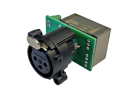
I've been using these transformer modules lately to either input or output balanced connections on my tube gear and they work great + is simple to install.

 
I've been using these transformer modules lately to either input or output balanced connections on my tube gear and they work great + is simple to install.

its a simple way to get an unbalanced line circuit to interface with balanced, however its not the wanted use case here.
 
Back
Top Bottom