

You are using an out of date browser. It may not display this or other websites correctly.
You should upgrade or use an alternative browser.
You should upgrade or use an alternative browser.
Seeking Soundcraftsmen DX4000 preamp op amp upgrade experience
- Thread starter Schmidlapper
- Start date
-
- Tags
- dx4000 question soundcraftsmen

Racingh11
Super Member
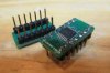
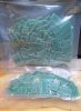
I also installed some SIOC OPA1604 on these input boards I made. The IC adapters came from Mouser at about $10 each plus shipping. I only bought them because I didn't want to wait for mine. I should be set for a while now, I have 200x 4136 and 100x TL084 pinout adapters printed. These boards were setup for balanced inputs for some Adcom GFA-565 amps, but they were designed for the Soundcraftsmen amps when all the parts are installed.


PabloTincho
Super Member
Can you install the LM4562 in those new boards ?
Racingh11
Super Member
The boards are for quad op-amp, the lm4562 is dual.Can you install the LM4562 in those new boards ?
PabloTincho
Super Member
Is there quad version of the lm4562 ?
Did the distortion numbers went down on the preamp ?
Did the distortion numbers went down on the preamp ?
Racingh11
Super Member
I'm not sure, I haven't put them in the DX4000 yet.Is there quad version of the lm4562 ?
Did the distortion numbers went down on the preamp ?
PabloTincho
Super Member
Since there is not a service manual for the soundcraftsmen pro control 4, how many op-amps and are they all RC4136 ?
PabloTincho
Super Member
are the pro control 4 and 3 pretty much a dx4000 ?
PabloTincho
Super Member
I wonder why they used the same op-amps ?
There were better op amps at the time
There were better op amps at the time

DirtyThirty
New Member
What ever became of this? Curious to know as I just picked up a DX4000

Schmidlapper
Super Member
the modern manufactured RC4136 is rated at 1.7 V/uS, almost double the original version, which I believe was 1, this should improve upon the calculated results considerably. Maybe not fast amongst newer chips, but as you have pointed out, capable of performing the task designed for. I too would love one day to see what the tests look like. Especially the as designed results, but too the newer chips.The main benefit to this upgrade would be lower noise and greater channel separation. I don't believe the 4136 restricted signals in the frequency and voltage range used in. The closest may have been the slew rate being 1V/uS compared to the 1604 20V/uS. But 1V/uS can support about 90khz at rated amp sensitivity, and about 16khz at 10V, which would be very high transient spikes. It may open up some sonics, but who knows what can be actually heard. I will try to see if I can measure a S/N difference and distortion. But I 'm not sure if I have any DX4000 around. I would have to use a DX4200 or something which makes it a little harder to swap chips quickly for comparison.

eizner23
Super Member
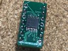
Can you assist with or submit photo of the orientation of 1604 chip on this adapter? I couldnt decipher what is pin 1.OPA1604
Racingh11
Super Member
To me it looks like the trace is broken on pin 1, and the chip is installed in the wrong orientation. The dot on the chip should line up with the mark on the screen print, right by where the trace is broken. It looks like you soldered it with a soldering iron or didn't use enough heat, where the chip should have been soldered with hot air, oven, or hot plate.This is what mine look like. I get no signal passed when i replace it with two other opamps. I did continuity test to make sure no SMD pins were shorted and was getting to the adapter pins.
View attachment 2968232
eizner23
Super Member
Thanks for the analysis. Pin 1 top right corner of pcb is what i was assuming. It looks like i need to flip the chip around. i guessed wrong on ic pin 1. Its hand soldered under mag glass with extra care, best i can do.To me it looks like the trace is broken on pin 1, and the chip is installed in the wrong orientation. The dot on the chip should line up with the mark on the screen print, right by where the trace is broken. It looks like you soldered it with a soldering iron or didn't use enough heat, where the chip should have been soldered with hot air, oven, or hot plate.
eizner23
Super Member
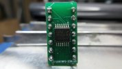
Nice work, what is your process? This is my first SMD project. Im in Madison if you offer this service.Here's a photo of one I had laying around
View attachment 2969039