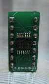
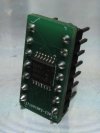
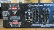
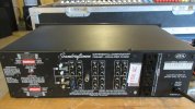
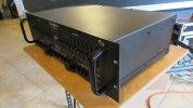
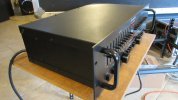
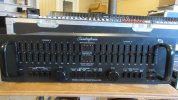
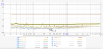
Well.. I still see a little fabric hair stuck to it, if that makes you feel better.

Hey Racingh11, any chance I can get 4 of those PCBs from you? I just got a DX4000 and I'm in the process of fixing some of the problems.
The opamps are all powered by the unregulated 17V rails (which are actually 22V rails, dropped to 17.4 with 220 Ohm resistors), even though the opamps are rated for a maximum +/- 18V. There's no margin for line voltage variations, etc. The -15V regulator is good for 1.5A but the +15 regulator is only good for 250 mA (why would they do something like that?). I'm replacing that regulator with a higher current capable part, and then wiring the opamps to the regulated 15V rails.
The two 470 uF bypass caps for the opamps are both located near the power supply, even though the opamps are far away. I've never built an opamp circuit that didn't have bypass caps (electrolytic or tantalum and ceramic) on each rail at each chip. I'll be adding some, maybe on the bottom of the PCB.
9 of the 15 button caps are missing or cracked and I haven't been able to find a replacement so I am going to 3D print them.
I just finished restoring my PM860 that I bought new in the early 80s. What a nightmare! The main power supply filter caps were rated for 75V even though the rails sit at 72V. It's a wonder they never blew up. I replaced those caps with some Kemet 13000 uF 100V parts rated for 18000 hours at 85C. I might have to replace them again in 100 years. I replaced all the other electrolytics with Nichicons, too.
I'm not overly impressed with SCs engineering. They skimped in so many ways- no silk screen layers on the PCBs identifying components, components operating at the edge of their specs, unmarked wires running everywhere. It takes a few hours of prep work tracing connections and identifying parts before you can even start on fixing anything. Ugh!