• The move to the new server is done. There are some software and database maintenance updates in process. This has us passing the hat around to help out. We appreciate any donations. Seriously, even a dollar helps. The payment page may be found here - https://www.audiokarma.org/support.html

Selecting a NTC thermistor inrush limiter

thorpej

AK Subscriber
Subscriber
Sorry folks, not strictly a tube audio issue, but my assumption is that folks here have some experience with it.

The amp design I'm working on will have a B+ current draw of approximately 450mA (that's rounded up) at full power. At idle it's going to be around 240mA (again, rounded up). B+ out of the voltage multiplier is 410V on paper. So that's 184.5VA and 98VA, respectively. So, that should be 1.6A on the PT primary at full power and 820mA at idle.

My plan was to put the thermistor on the neutral lead of the PT.

The 120 ohm Amphenol CL-90 is rated for a steady-state current of 2A, and is what I'm leaning toward using. The data sheet states that at 50% rated load (around what I'll be idling at), it will have a resistance of 3 ohms. At 75% rated load (about what my max power draw will be), it'll be 1.75 ohms.

On the surface, this seems like the correct part to choose, but I'm not sure about the max energy rating (36 Joules for the CL-90). Is this something I really need to worry about? All of the example circuits I've seen for these parts are in switching power supplies, and the location of the thermistor isn't where I intend to put it.

Advice, anyone?
 
Register to hide this ad
cl-80 and cl-90 are the 2 most widely used inrush I-limiters.
some stik em in both xfmr input lines and some only in 1.
After install, check your B+ to see if it has been changed.
You may need to do some fiddling.
You can get em by the handfull on the bay dirt cheep.
No need for the big name brands. IMO
 
I was just looking at thermistors for my mew amp build as well since I seem to have used up all of what I had. As long as your fuse value is less than the steady state current rating of your thermistor, you should be fine. Assuming you use a 1.5 or 2 A fast blow, a 2A thermistor should be plenty. You would expect the fuse to give up the ghost well before your thermistor. I bought CL-80 equivalents (MF72-47D15 - 47ohm/3A) at a fraction of the CL-80 price from a Chinese E-Pray vendor. The plan is to put one in each arm of the AC inputs.

Don't limit yourself to the CL series. Here's a chart of all the possibilities of the MF series.

EDIT: Oh yeah, before I forget, try and place them away from any heat sensitive components with some room to breathe. They can get a little toasty....
 
What are you trying to protect? Cold starts? Hot starts? SS rectifier? Tube rec.?

Yah, sorry, I suppose I should have provided more detail.

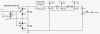
Here's the schematic of my somewhat absurd power supply.

Screen Shot 2016-06-09 at 10.32.16 AM.png

I get 78VAC out of the transformer secondary, which then goes into the voltage quadrupler. The 10A07 diodes have a surge current rating of 600A and a forward current rating of 10A -- they're beefy and won't even break a sweat in this circuit.

The intent of using a thermistor was simply to soften the blow of charging up those 4 800uF caps at cold start.
 
Last edited:
Both legs of the AC line is where I put them on my Heathkit W4AM amps.

There ya go, and I buy mine from Mouser FWIW. The voltage ratings on these devices must be awfully conservative on the data sheets. I have used them up to ~500v (a CL120) with no failures.
 
You can reflect your power supply secondary side capacitance back to the primary side voltage and compare the NTC 'max capacitance at a primary voltage' rating with what your circuit loads the NTC with. You can also estimate the additional influence of heater in-rush and transformer in-rush and see if a particular NTC has enough energy throughput margin for your amp. For big amps or amps with way toooo much filter capacitance, and normal commercial NTC selections, you may have to use two NTC in series to cover the energy throughput needs - I had to use two NTC in series for a big amp I am preparing on the bench.

There are some design examples in:
http://dalmura.com.au/projects/Valve amp fusing.pdf
 
Thanks, @trobbins, that's helpful. In my case, the filaments are powered with a separate transformer (the PT I'm using for B+ was originally designed for 100W solid state bass amps).
 
I would recommend only putting switches, fuses, NTC in mains active side. That minimises the wiring and parts that could remain 'active' if a fault occurs in switch or NTC or transformer primary.
 
Sorry folks, not strictly a tube audio issue, but my assumption is that folks here have some experience with it.

The amp design I'm working on will have a B+ current draw of approximately 450mA (that's rounded up) at full power. At idle it's going to be around 240mA (again, rounded up). B+ out of the voltage multiplier is 410V on paper. So that's 184.5VA and 98VA, respectively. So, that should be 1.6A on the PT primary at full power and 820mA at idle.

My plan was to put the thermistor on the neutral lead of the PT.

The 120 ohm Amphenol CL-90 is rated for a steady-state current of 2A, and is what I'm leaning toward using. The data sheet states that at 50% rated load (around what I'll be idling at), it will have a resistance of 3 ohms. At 75% rated load (about what my max power draw will be), it'll be 1.75 ohms.

On the surface, this seems like the correct part to choose, but I'm not sure about the max energy rating (36 Joules for the CL-90). Is this something I really need to worry about? All of the example circuits I've seen for these parts are in switching power supplies, and the location of the thermistor isn't where I intend to put it.

Advice, anyone?

I would put it on primary side right after fuse and power switch on hot side. But are you sure that 2 amps rating is sufficient? It is less than 240 watts. Also maximum current flow is too low. Consider that for few tens of a second transformer is loaded practically by short circuit before capacitors are charged. Inrush current can be in tens of amperes and your thermistor needs to tolerate it.
 
I would recommend only putting switches, fuses, NTC in mains active side. That minimises the wiring and parts that could remain 'active' if a fault occurs in switch or NTC or transformer primary.

I usually wire my power switch after the fuse, so I'll go ahead and put the NTC on the hot lead as well.
 
I would put it on primary side right after fuse and power switch on hot side. But are you sure that 2 amps rating is sufficient? It is less than 240 watts. Also maximum current flow is too low. Consider that for few tens of a second transformer is loaded practically by short circuit before capacitors are charged. Inrush current can be in tens of amperes and your thermistor needs to tolerate it.

2A is the steady-state rating for the CL-90. Isn't the point of the thermistor to limit the in-rush current?

(I should clarify the schematic somewhat -- the 2A rating for the fuse is wrong, and is shown in the wrong location, because the mains fuse is feeding 3 separate transformers .. the B+ PT, the separate filament PT, and the separate bias PT.)
 
2A is the steady-state rating for the CL-90. Isn't the point of the thermistor to limit the in-rush current?

(I should clarify the schematic somewhat -- the 2A rating for the fuse is wrong, and is shown in the wrong location, because the mains fuse is feeding 3 separate transformers .. the B+ PT, the separate filament PT, and the separate bias PT.)

So you say that under steady state your amplifier consumes 2 amps? What is the output power? Did you try to check how much current is there using tools like KillAWatt?
 
So you say that under steady state your amplifier consumes 2 amps? What is the output power? Did you try to check how much current is there using tools like KillAWatt?

Under full power, my (perhaps incorrect) math tells me that I'll be drawing 1.57A on the primary side of the HV transformer. It will not be consuming that much most of the time :-) The filament transformer will be pulling another 275mA on the primary... so I guess a 2A fuse would be fine (I must have mis-calculated the current requirements of the filament transformer before).

It's stereo 6L6GC push-pull amp, and the math tells me 25-30W/ch.
 
Yummy! 6L6 amps are my favorite. Tell us more if you have time.

It's basically the Mullard 5-20 front end (with a 12AX7 instead of an EF86, a'la the Eico HF-87/89), using a solid state CCS in the inverter tail. Output stage is ultra-linear connected pair of 6L6GC. It started out as a thought exercise of what I could build with these MusicMan power transformers I picked up at a fire sale, and I plan to actually build it sometime this summer.
 
Eico circuit is a popular circuit with great results. I never had luck with ccs and always went back to a resistor. I'll be interested how you make out ? Your power supply is also interesting. Enjoy the summer.....
 
I really wouldn't be overly concerned about protecting solid state rectifiers. They're cheap as chips, even if you use fancy ones.
 
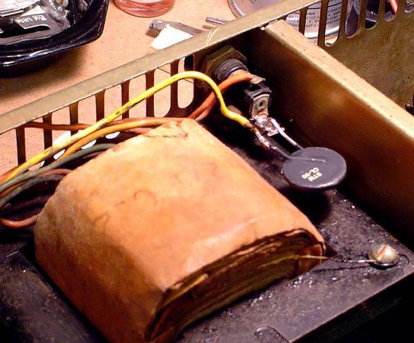
CL90 just past the fuse for me. CL80 does have a higher amp rating, but the CL90 has a larger surface for improved heat dissipation, and I haven't had one fail even under extreme conditions pulling way more than their rating. This one's mounted on a ham radio that's listed at 6 amps max draw ...

thermister.jpg


Been doing the duty for years now.

And +1 on max clearance around them ... these puppies get HOT.

Oh. DO measure your B+ after installing the thermister ... they never open up completely, and you'll be missing a few volts. Usually not an issue unless you were borderline to begin with.
 
Back
Top Bottom