

You are using an out of date browser. It may not display this or other websites correctly.
You should upgrade or use an alternative browser.
You should upgrade or use an alternative browser.
Serious design effort begins on mini-console project
- Thread starter mashaffer
- Start date

mashaffer
Super Member
Oops just realized that this will not have enough gain for the iPod or even a CDP to get full output. The preamp section is a bit less than unity gain due to the FB tone control section. The mu of the 6N1P in the power amp is only about 35 so there is no way that a 1V peak (1.4V RMS) input can swing the KT-88 grids +/- 40V. Even a 12AX7 would be hard pressed to get enough of a drive voltage even without the FB.
A suggestion on another forum that the Schade would work better with pentode drivers presents an interesting possibility if a gain of solidly over 100 were possible. However I suppose the easiest solution is an additional CC stage after the tone controls. A 6N1P should be sufficient. There is an unused 7 pin socket on the preamp chassis which I could enlarge for an extra 9 pin socket.
mike
A suggestion on another forum that the Schade would work better with pentode drivers presents an interesting possibility if a gain of solidly over 100 were possible. However I suppose the easiest solution is an additional CC stage after the tone controls. A 6N1P should be sufficient. There is an unused 7 pin socket on the preamp chassis which I could enlarge for an extra 9 pin socket.
mike

Scuzzer
Fixed Bias
Control range is about +/- 12dB if I remember correctly.
No wiggle room there then. I always struggle with getting enough gain when using an mp3 player as the source. Mine has less than 1v output though.
mashaffer
Super Member
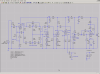
I know, I know... am I ever going to start slinging solder on this thing? A good sign is that I have started making a list of parts to dig out of the parts bin. I did some more simulation work and this is where I am currently sitting (ignore the 214V tag by U3 I forgot to delete it on the last update).

- I added U4 as a gain stage after the tone controls. My original approach was to add a 6CG7 stage here as I didn't need tons of gain. After looking at that I realized the the 6CG7 stage would have a much larger allowable voltage input than the following driver stage (6N1P) and that the 6N1P driver would be right at the ragged edge trying to swing the required voltage for the KT-88s at full output. So I decided to switch the driver and gain stage tubes. Also decided to go 12AY7 for better microphonics.
- I simulated using 12AY7 in all preamp positions because of the freedom from microphonics. I only have one 12AY7 on hand though so the beta test version may use the AY only in the gain stage with the 12AX7 and 12AU7 used as in the previous schematic.
- I also changed several capacitor values to more reasonable choices. The coupling cap to the driver tube is intentionally chosen to limit frequencies below 30 Hz or so to avoid wasting power on frequencies that the main speakers can't reproduce anyway. Since I have adequate gain now I may even put a second order network in there instead for better filtering.
- I also don't have a 6CG7 on hand (but lots of Baldwin 12AU7s) so I checked and the bias shift between the two tubes in only about 10% 10.5V (6CG7) to 11V+ (12AU7) so I will probably just build the prototype with a 12AU7 in that spot. I would only have to make a quick change to the heater wiring then to put in the 6CG7. I know that in theory the 12AU7 will not be as linear but this is fine for prototyping and besides I have heard that it is not that bad at these lower plate currents. The main thing is that it will have the right gain and headroom so I can determine if the overall design is proper.
- I added R18 to accomplish two things. (1) increasing the FB ratio and (2) making the feedback ratio less dependent on the variable rp of the driver. The value of 22K was chosen when I had the 6N1P in that position as it seemed that it should give approximately the ratio that Schade recommended. In that simulation it increased the FB from 2dB (Aol/Acl) to 6dB which seemed like a good starting point. With the 6CG7 in that position it was increase to 7.5dB. On the "in the flesh" prototype I can twiddle that value for the best results.
- If in the final analysis the gain is too high I can either switch to un-bypassed cathode bias resistor on the gain stage or add a little bit of local FB to it as well.
- I may also switch to voltage divider bias on the input CF too as I think that is usually the preferred method unless ultra high Zin requirement suggests the bootstrap type shown.
I welcome any comments.
mike
- I added U4 as a gain stage after the tone controls. My original approach was to add a 6CG7 stage here as I didn't need tons of gain. After looking at that I realized the the 6CG7 stage would have a much larger allowable voltage input than the following driver stage (6N1P) and that the 6N1P driver would be right at the ragged edge trying to swing the required voltage for the KT-88s at full output. So I decided to switch the driver and gain stage tubes. Also decided to go 12AY7 for better microphonics.
- I simulated using 12AY7 in all preamp positions because of the freedom from microphonics. I only have one 12AY7 on hand though so the beta test version may use the AY only in the gain stage with the 12AX7 and 12AU7 used as in the previous schematic.
- I also changed several capacitor values to more reasonable choices. The coupling cap to the driver tube is intentionally chosen to limit frequencies below 30 Hz or so to avoid wasting power on frequencies that the main speakers can't reproduce anyway. Since I have adequate gain now I may even put a second order network in there instead for better filtering.
- I also don't have a 6CG7 on hand (but lots of Baldwin 12AU7s) so I checked and the bias shift between the two tubes in only about 10% 10.5V (6CG7) to 11V+ (12AU7) so I will probably just build the prototype with a 12AU7 in that spot. I would only have to make a quick change to the heater wiring then to put in the 6CG7. I know that in theory the 12AU7 will not be as linear but this is fine for prototyping and besides I have heard that it is not that bad at these lower plate currents. The main thing is that it will have the right gain and headroom so I can determine if the overall design is proper.
- I added R18 to accomplish two things. (1) increasing the FB ratio and (2) making the feedback ratio less dependent on the variable rp of the driver. The value of 22K was chosen when I had the 6N1P in that position as it seemed that it should give approximately the ratio that Schade recommended. In that simulation it increased the FB from 2dB (Aol/Acl) to 6dB which seemed like a good starting point. With the 6CG7 in that position it was increase to 7.5dB. On the "in the flesh" prototype I can twiddle that value for the best results.
- If in the final analysis the gain is too high I can either switch to un-bypassed cathode bias resistor on the gain stage or add a little bit of local FB to it as well.
- I may also switch to voltage divider bias on the input CF too as I think that is usually the preferred method unless ultra high Zin requirement suggests the bootstrap type shown.
I welcome any comments.
mike
Attachments
mashaffer
Super Member
I haven't updated this thread in quite a while so I thought I would let you know how things are going.
Well if necessity is the father of invention, then certainly poverty is it's mother. I have been wiring up the power amp chassis bit by bit (some nights just a couple of connections even) and have gotten to the point that I need to start putting on the iron and the can cap to continue. I have oft wished for one of the rotating cradles for working with awkward chassis for when one gets to this point.
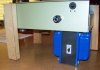
Well I don't have the extra money for one of those but I did have some scrap wood lying around. No, I am not one of those wizards that can transform a hunk of OSB into a fancy tool but my chassis like many others has screw holes for mounting...

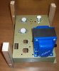
Cut to the same height as the power transformer and...

..presto. OK so it ain't pretty but it beats trying to work on a chassis propped up on rolls of electrical tape and spare tools.
Anyway I have done most of the wiring that I can do without the cap and iron mounted. I have a long way to go before I am as neat as some of you guys but no doubt each project will get a little better than the last.

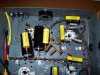
The two KT88s go on the top two sockets with the 6CG7 on the lower left and the rectifier on the lower right. You will note that the cathode caps on the 6CG7 are a lot larger than those on the KT88s (33u v.s. 22u). Seems a little bit backward I know but they fit better that way and both are sufficiently large for the application since there will be a 40Hz 2nd order high pass before the power amp input. Also having the smaller value on the output tubes may be better for blocking under overload.
You can't see it in the picture but the caps on the 6CG7 stick way up high so there is plenty of clearance below them. Notice that each electrolytic is bypassed by a polyester film cap (.15u for the 33u caps and .1u for the 22u caps). Since the resistors were not long enough to span the distance to the tag strip I used the big cap for that and then piggybacked the other components to it. Not neat but should be OK. The cathode resistors for the 6CG7 are carbon film instead of metal film only because I neglected to order the right ones. I had intended to use 3.3k but simulation indicates that the 3k that I had should be fine. A little less cathode voltage 9V instead of closer to 10V and 3mA instead of 2.8mA. If it doesn't work out at least they are easy to get to.
On the PT Brown is the 6V heaters, Yellow is the 5V and red is the B+ winding. Once the routing is finalized I will use plastic loops to cinch them down into place. The can cap will go in the hole without the insulator as it is farthest from the power and rectifier tubes (cooler). I intend to clamp all ground returns with an eyelet at the screw hole for the can cap's clamp.
The two 100 ohm power resistors on the rectifier are to provide some safety margin for the 5AR4 rectifier since I am using new manufacture Russians.
At the top you see the grommets for the leads from the OPTs which will be mounted on that side sticking out sideways. One PS choke will be directly under the PT and the other sticking out the side (back) using the same mounting bolts for each. The choke under the transformer will just clear the fuse holder (got lucky there).
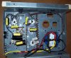
A closer look at the input side...

You can see the 1k carbon comp grid stoppers on the 6CG7 (to the lower right you can see one on one of the KT88s too). They look old school but they are brand new. The socket was so close to the input jacks that I figured that shielded cable was unnecessary. Hopefully I was right but we shall see.
As always criticism is welcome.
Oh, and a question. I know that there is no need to twist the anode tap and UL tap together since the current flows the same direction in each but is there any reason not to do it? It would be a bit more convenient for routing purposes.
mike
Well if necessity is the father of invention, then certainly poverty is it's mother.
I have been wiring up the power amp chassis bit by bit (some nights just a couple of connections even) and have gotten to the point that I need to start putting on the iron and the can cap to continue. I have oft wished for one of the rotating cradles for working with awkward chassis for when one gets to this point.Well I don't have the extra money for one of those but I did have some scrap wood lying around. No, I am not one of those wizards that can transform a hunk of OSB into a fancy tool but my chassis like many others has screw holes for mounting...
Cut to the same height as the power transformer and...
..presto. OK so it ain't pretty but it beats trying to work on a chassis propped up on rolls of electrical tape and spare tools.
Anyway I have done most of the wiring that I can do without the cap and iron mounted. I have a long way to go before I am as neat as some of you guys but no doubt each project will get a little better than the last.
The two KT88s go on the top two sockets with the 6CG7 on the lower left and the rectifier on the lower right. You will note that the cathode caps on the 6CG7 are a lot larger than those on the KT88s (33u v.s. 22u). Seems a little bit backward I know but they fit better that way and both are sufficiently large for the application since there will be a 40Hz 2nd order high pass before the power amp input. Also having the smaller value on the output tubes may be better for blocking under overload.
You can't see it in the picture but the caps on the 6CG7 stick way up high so there is plenty of clearance below them. Notice that each electrolytic is bypassed by a polyester film cap (.15u for the 33u caps and .1u for the 22u caps). Since the resistors were not long enough to span the distance to the tag strip I used the big cap for that and then piggybacked the other components to it. Not neat but should be OK. The cathode resistors for the 6CG7 are carbon film instead of metal film only because I neglected to order the right ones. I had intended to use 3.3k but simulation indicates that the 3k that I had should be fine. A little less cathode voltage 9V instead of closer to 10V and 3mA instead of 2.8mA. If it doesn't work out at least they are easy to get to.
On the PT Brown is the 6V heaters, Yellow is the 5V and red is the B+ winding. Once the routing is finalized I will use plastic loops to cinch them down into place. The can cap will go in the hole without the insulator as it is farthest from the power and rectifier tubes (cooler). I intend to clamp all ground returns with an eyelet at the screw hole for the can cap's clamp.
The two 100 ohm power resistors on the rectifier are to provide some safety margin for the 5AR4 rectifier since I am using new manufacture Russians.
At the top you see the grommets for the leads from the OPTs which will be mounted on that side sticking out sideways. One PS choke will be directly under the PT and the other sticking out the side (back) using the same mounting bolts for each. The choke under the transformer will just clear the fuse holder (got lucky there).
A closer look at the input side...
You can see the 1k carbon comp grid stoppers on the 6CG7 (to the lower right you can see one on one of the KT88s too). They look old school but they are brand new. The socket was so close to the input jacks that I figured that shielded cable was unnecessary. Hopefully I was right but we shall see.
As always criticism is welcome.
Oh, and a question. I know that there is no need to twist the anode tap and UL tap together since the current flows the same direction in each but is there any reason not to do it? It would be a bit more convenient for routing purposes.
mike
Attachments
Last edited:
mashaffer
Super Member
Well, it is finally playing music (at least the power amp). I haven't updated my personal web page but just a quick update. I changed a few values such as the 6CG7 bias resistors to 3k instead of 3.3k as that is what I had available. Same with some of the caps. At some point I will update the schematic with actual values.
After wiring it all up I brought it up with no tubes in using a variac and checked PT winding voltages and all looked good. I used a 3A fast blow fuse for the testing. When this checked out I put in all of the tubes (KT88 and 6CG7) except the rectifier just to make sure that heater wiring was OK. Again everything was OK.
Now the big test. I put in the rectifier tube and brought it up on the variac. Just to be sure I wouldn't blow her brand new 5AR4 rectifier I put in a used 5U4GB instead. I checked B+ as well as the cathode voltages. KT88 came out about right at 38V or so but the 6CG7 was rather high at almost 16V instead of just shy of 10V. I checked anode voltages on the 6CG7 and found them very low (in the 90s). So I looked around to figure out what was wrong. (Insert sheepish grin) I forgot the grid leaks. Oops. Put in some 470k grid leaks and it biased up just perfectly.
So the final test for the night was to hook up an iPod dock through a cheap 80s vintage radio shack mic mixer and see if it made music. To cut to the chase I could hear no hum but the music was strong and as well balanced as I could expect through my test speakers. The speakers are 6.5" 8 ohm automobile tri-ax stuck in an arbitrary sealed (or at least mostly sealed) enclosure. The OPTs are 4 ohm only so the load was not ideal but I got loud clean sound within the limits of the test setup.
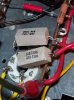
I listened to it for about half an hour and nothing seemed to get really out of whack. The 10 watt power resistors on the rectifier plates got quite hot to the point that I could not hold my finger on them for more than a second but they didn't seem to continue getting hotter or to discolor at all. A little odor but not bad. I think that they should be OK but it would be nice if at some point I can get a thermometer to check it out.
Next time I will try with the other rectifier and also try it directly plugged in instead of through the variac just to make sure everything is OK. After that it is time to try with the right speakers (though still in the wrong cabinet) and run it for long term testing. Oh, and I probably ought to ground the OPT secondaries. Right now they are floating but it shouldn't affect the sound since there is no gNFB around the tranny.
After wiring it all up I brought it up with no tubes in using a variac and checked PT winding voltages and all looked good. I used a 3A fast blow fuse for the testing. When this checked out I put in all of the tubes (KT88 and 6CG7) except the rectifier just to make sure that heater wiring was OK. Again everything was OK.
Now the big test. I put in the rectifier tube and brought it up on the variac. Just to be sure I wouldn't blow her brand new 5AR4 rectifier I put in a used 5U4GB instead. I checked B+ as well as the cathode voltages. KT88 came out about right at 38V or so but the 6CG7 was rather high at almost 16V instead of just shy of 10V. I checked anode voltages on the 6CG7 and found them very low (in the 90s). So I looked around to figure out what was wrong. (Insert sheepish grin) I forgot the grid leaks. Oops. Put in some 470k grid leaks and it biased up just perfectly.
So the final test for the night was to hook up an iPod dock through a cheap 80s vintage radio shack mic mixer and see if it made music. To cut to the chase I could hear no hum but the music was strong and as well balanced as I could expect through my test speakers. The speakers are 6.5" 8 ohm automobile tri-ax stuck in an arbitrary sealed (or at least mostly sealed) enclosure. The OPTs are 4 ohm only so the load was not ideal but I got loud clean sound within the limits of the test setup.
I listened to it for about half an hour and nothing seemed to get really out of whack. The 10 watt power resistors on the rectifier plates got quite hot to the point that I could not hold my finger on them for more than a second but they didn't seem to continue getting hotter or to discolor at all. A little odor but not bad. I think that they should be OK but it would be nice if at some point I can get a thermometer to check it out.
Next time I will try with the other rectifier and also try it directly plugged in instead of through the variac just to make sure everything is OK. After that it is time to try with the right speakers (though still in the wrong cabinet) and run it for long term testing. Oh, and I probably ought to ground the OPT secondaries. Right now they are floating but it shouldn't affect the sound since there is no gNFB around the tranny.
mashaffer
Super Member
Proof.
http://www.youtube.com/watch?v=0bt6SEw4Yvw
The warm glow...

The messy layout (which oddly enough is free of hum and noise)...

And the power resistors that get nice and toasty...

http://www.youtube.com/watch?v=0bt6SEw4Yvw
The warm glow...
The messy layout (which oddly enough is free of hum and noise)...
And the power resistors that get nice and toasty...
Attachments


mashaffer
Super Member
Thanks Shelly_d and Keg!Last night I felt bold enough to try the new 5AR4 regulator and to my surprise the results were exactly what I expected. The final HT voltage was about 20 volts higher but the surge at turn on was much less. Instead of hitting the first filter cap with its rated WVDC of 550V as with the 5U4GB the 5AR4 produce a peak under 500V. Maybe I am too timid but I prefer to never exceed the working voltage rating even at turn on.
Will do a little more diddling with voltage measurements in order to calculate the power dissipation in those rectifier plate resistors and if it seems OK I will be taking it downstairs and giving it some long term workout with the intended speakers.
Another thing that occurred to me was that given the location of those power resistors above (when the amp is upside down like this) the rectifier they are exposed to quite a bit of heat rising up from the rectifier tube itself (which gets rather warm too) so maybe the amount of heat at the resistors will be reduced when righted. There is quite a bit of room for air circulation under the chassis due to its design. In the final unit the bottom of the console cabinet below the PA chassis will be vented also.
Played a wide variety of music on it last night too. Given that I am using a cheap solid state mixer as a preamp it was rather interesting. A little Boston... good solid bass... maybe a hint of congestion on complex passages but we will see with some better speakers. A little opera (Mozart's Figaro)... nice and clean with no sense of overload on the soprano or large ensemble sections. Some a cappella hymns in the style of "The Regeneration"... stunningly moving... I hadn't realized how closely mic'ed this recording was. It was like they were standing right in front of me. I could hear every breath.
Just can't decide whether to build proper speaker enclosures first (to get a feel for the bass possibilities) or to build the preamp next (to get that mixer out of the equation).
mashaffer
Super Member
I measured AC and DC voltage across each resistor and got 16.5 and 8.5 respectively on each resistor. If they are additive and I did the calculations right that is 6 1/4 watts. If they are 10W parts I suppose that is OK but pushing a little harder that I probably ought in a confined space. If they are 5 watt parts it is too much. I think that I could probably switch to 50 ohm 10W instead of 100 ohm and still have reasonable protection for the rectifier and cut the dissipation down to 1/4 of what it currently is. Wonder if the shack has them...
mashaffer
Super Member
I got some 50 ohm resistors from radio shack. They were physically much longer but I got them to fit. The voltages went up some more but the resistors run much cooler. They do get hot to the touch but I am able to keep my finger on them for several seconds without pain.
For reference I relink the schematic...
A few things have changed.
- The cathode resistor on the 6CG7 is 3K instead of 3.3k and is bypassed.
- The KT88 cathode resistor is a 1.1k and 1.2k 3 watt in parallel (574 ohms).
- Coupling cap is .47u instead of .68u.
I made the following measurements.
- B+ at the entrance to the OPT: 472V
- KT88 plate voltage: 460V
- KT88 Cathode voltage: 43V ==> 75mA
- KT88 Dp = (460 - 43) * 0.075 = 32W
- B+ at 6CG7: 454
- 6CG7 Plate Voltage: 263V
- 6CG7 Cathode Voltage: 10.5V ==> 3.5mA
- 6CG7 Dp = (263 - 10.5) * .0035 = 884mW
So it seems like I am running things pretty conservatively which is what I intend given the close quarters in the final application. Also, if I am reading the data sheet for the 5AR4 correctly I should be OK even if I end up close to 200mA with the preamp section added since the DCV at the input to the first filter cap is under 500V.
Any thoughts on my operating points regarding either durability or fidelity?
For reference I relink the schematic...
A few things have changed.
- The cathode resistor on the 6CG7 is 3K instead of 3.3k and is bypassed.
- The KT88 cathode resistor is a 1.1k and 1.2k 3 watt in parallel (574 ohms).
- Coupling cap is .47u instead of .68u.
I made the following measurements.
- B+ at the entrance to the OPT: 472V
- KT88 plate voltage: 460V
- KT88 Cathode voltage: 43V ==> 75mA
- KT88 Dp = (460 - 43) * 0.075 = 32W
- B+ at 6CG7: 454
- 6CG7 Plate Voltage: 263V
- 6CG7 Cathode Voltage: 10.5V ==> 3.5mA
- 6CG7 Dp = (263 - 10.5) * .0035 = 884mW
So it seems like I am running things pretty conservatively which is what I intend given the close quarters in the final application. Also, if I am reading the data sheet for the 5AR4 correctly I should be OK even if I end up close to 200mA with the preamp section added since the DCV at the input to the first filter cap is under 500V.
Any thoughts on my operating points regarding either durability or fidelity?

Kegger
R.I.P. 1/12/1966 - 6/1/2017
I like the KT88 operating point, but I'd probably up the 6CG7 current, and no problem
since you have plate voltage to spare, I'd go for say 6 or 7ma there, maybe try like a
1.2-1.5k cathode resistor on it an see how it works out.
Also what is your power supply configuration?
Curious, what's the purpose of R18? Or more appropriately did you come up with that
on your own, or find info about it? It looks as if it helps get you more feedback but at
the same time drop very very little voltage from the output to the drivers plate. humm :scratch2:
since you have plate voltage to spare, I'd go for say 6 or 7ma there, maybe try like a
1.2-1.5k cathode resistor on it an see how it works out.
Also what is your power supply configuration?
Curious, what's the purpose of R18? Or more appropriately did you come up with that
on your own, or find info about it? It looks as if it helps get you more feedback but at
the same time drop very very little voltage from the output to the drivers plate. humm :scratch2:
mashaffer
Super Member
Thanks. Will take a look at that. I have been running continuous music for almost 3 hours now and I don't smell anything amiss. Are you looking for improved linearity with the higher plate current in the driver?
PS configuration is PT ==> 50 0hm power resistors ==> 5AR4 ==> CLCLC filter of C=40u and L=4H. DCR on the chokes is on the order of 60 ohms IIRC.
Actually I can not take credit for R18. I came across that idea in one of the forums. The idea is to increase the impedance that the feedback is operating into and to reduce its dependence on rp.
Are you looking for improved linearity with the higher plate current in the driver?PS configuration is PT ==> 50 0hm power resistors ==> 5AR4 ==> CLCLC filter of C=40u and L=4H. DCR on the chokes is on the order of 60 ohms IIRC.
Actually I can not take credit for R18. I came across that idea in one of the forums. The idea is to increase the impedance that the feedback is operating into and to reduce its dependence on rp.
Kegger
R.I.P. 1/12/1966 - 6/1/2017
More current for the driver was for both linearity and "drive" capability.
-----------
Looking into that R18, I see how it could be handy, but if I've gotten a
handle on it's implications it's going to add to the output impedance of
the driver stage, now driving into this output section and it's fairly high
grid circuit resistance may still be alright, but if I am correct you might
want to try dropping that R18 to say 10k or less then dropping that R4
to compensate for the loss in feedback.
I like the idea behind this resistor, and I could see it helping a low plate
resistance driver tube utilize schade feedback easier, just need to do a
bit of experimenting to see how best to utilize it, I will be trying it out. :thmbsp:
As to your power supply, you could use an smaller first cap in your supply
drop off a bit of voltage then probably do away with your 50ohm resistors.
(just info to ponder)
-----------
Looking into that R18, I see how it could be handy, but if I've gotten a
handle on it's implications it's going to add to the output impedance of
the driver stage, now driving into this output section and it's fairly high
grid circuit resistance may still be alright, but if I am correct you might
want to try dropping that R18 to say 10k or less then dropping that R4
to compensate for the loss in feedback.
I like the idea behind this resistor, and I could see it helping a low plate
resistance driver tube utilize schade feedback easier, just need to do a
bit of experimenting to see how best to utilize it, I will be trying it out. :thmbsp:
As to your power supply, you could use an smaller first cap in your supply
drop off a bit of voltage then probably do away with your 50ohm resistors.
(just info to ponder)
mashaffer
Super Member
Thanks Keg. I was not using the resistors on the rectifier to lower voltage but to limit inrush current to protect less than NOS quality rectifiers from arc over and to hopefully reduce the danger in hot switching. Since my filter caps are in the form of a multi section can lowering the first cap value is not as trivial as one might wish.
As to R18 value raising the driver stage I understood that this was not necessarily a bad thing as a pentode is often recommended for this circuit. Glad to hear that you are going to be on the case as I know we will learn interesting things from your work.
As to R18 value raising the driver stage I understood that this was not necessarily a bad thing as a pentode is often recommended for this circuit. Glad to hear that you are going to be on the case as I know we will learn interesting things from your work.
Kegger
R.I.P. 1/12/1966 - 6/1/2017
Yep I understood why you were using the 50ohm resistors, my thoughts were with
the small cap the resistors would be unnecessary as it would lower the stress with
dropping some of the voltage at the same time, so the drop of the resistors would
be redundant to drop caused by the smaller cap(in others same type drop as well).
I just see it as a more "elegant" solution if you will, just a thought, but if it's more
trouble then it's worth maybe not as practical here..
------- schade feedback and driver
Raising the plate resistance by using pentodes is good in the fact that like we know
schade feedback is easier to get more, But that plate resistance is in parallel with a
load resistor your using an with a pentode will tend to be small so the impedance of
the output of the stage will remain relatively low, by adding this R18 it's in series an
will Add to the overall output impedance of that driver stage, which would be higher
then using a pentode with say a 10k plate load resistor. (follow what I'm getting at?)
So say your pentode driver stage has a 1m plate resistance tube and a 10k load, the
output impedance will be dominated by the load resistor an somewhat lower then 10k.
Now take a triode with 7k plate resistance an a 47k plate load resistor, parallel those
and your less then 7k output impedance, but then add in the 22k R18 directly to that
and it raises your output impedance by that much, which is pretty drastic.
the small cap the resistors would be unnecessary as it would lower the stress with
dropping some of the voltage at the same time, so the drop of the resistors would
be redundant to drop caused by the smaller cap(in others same type drop as well).
I just see it as a more "elegant" solution if you will, just a thought, but if it's more
trouble then it's worth maybe not as practical here..
------- schade feedback and driver
Raising the plate resistance by using pentodes is good in the fact that like we know
schade feedback is easier to get more, But that plate resistance is in parallel with a
load resistor your using an with a pentode will tend to be small so the impedance of
the output of the stage will remain relatively low, by adding this R18 it's in series an
will Add to the overall output impedance of that driver stage, which would be higher
then using a pentode with say a 10k plate load resistor. (follow what I'm getting at?)
So say your pentode driver stage has a 1m plate resistance tube and a 10k load, the
output impedance will be dominated by the load resistor an somewhat lower then 10k.
Now take a triode with 7k plate resistance an a 47k plate load resistor, parallel those
and your less then 7k output impedance, but then add in the 22k R18 directly to that
and it raises your output impedance by that much, which is pretty drastic.