• The move to the new server is done. There are some software and database maintenance updates in process. This has us passing the hat around to help out. We appreciate any donations. Seriously, even a dollar helps. The payment page may be found here - https://www.audiokarma.org/support.html

Servicing a TASCAM 34

Adinol

Member
Greetings!

I "recently" got a good deal on a TASCAM 34. If memory serves me, it was $50 (or was it $80) cash on Craig's List and when I explained to the seller that it was for my kid, the seller threw in a 1970's Japanese acoustic guitar and a TASCAM PortaStudio. It was a great deal. He told me the TASCAM 34 would need some work - definitely a new belt and pinch roller.

Here is what the pinch roller looked like.
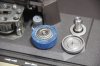
IMG_8190.jpg
I decided to make my own pinch roller tire. Here is how I made it.

I removed the painter's tape. I bought a rubber rod from McMaster Carr and bored a 11/16" hole in the rubber, then snugly placed it over the original pinch roller. I also made a cutter for the rubber, out of a piece of spring steel that I bent into a U shape, sharpened and mounted over a scrap piece (as a holder). I was considering to keep the rubber in the freezer before proceeding with the turning, but was too impatient, so I did the cutting at room temperature. I also had to make a jig to hold the pinch roller on the lathe. I cut it to a 32mm diameter.

Here are a couple of photos that show the work, my jig and the cutter.

IMG_0888_2.jpg

IMG_0889_2.jpg

I can't be sure that it will work without skewing the tape, but I will test it on junk tape and if there's a problem I will just get a proper replacement. This is really just to have a way of testing the machine while I'm servicing it. So, if I manage to fix the rest of the machine, at some point I will get a proper replacement.

When I opened the machine I discovered a loose spring. Here's a picture, next to the pinch roller (for size comparison). Perhaps someone here can tell me where this spring came from. One clue is also the grease that I see on the spring.
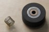
IMG_0893_2.jpg

Any ideas where this spring came from?

The machine needs a new belt, however, I discovered that the drive motor does not spin. I took some troubleshooting steps, to eliminate some possibilities.

So, here are the steps I took.

When I engage the tension arm the drive motor does not start spinning. I first suspected the switch on the tension arm (which I see is actually a light sensor), however, when I press PLAY (with the tension arm engaged) the take-up reel starts spinning. But it only spins for one second, then stops.

I opened the machine and discovered 8 fuses. They are all good.

Nothing is burned inside the machine (but I did not disassemble it entirely, yet) and the drive motor looks OK. Also, I am able to turn the shaft of the drive motor with my hand, so it is not stuck/glued in place.

I can see that the drive motor connects to a small PCB at the left side of the machine. Nothing burned there.
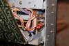
IMG_0894_2.jpg

I see that PCB has a connector with 8 terminals. I am imagining that I should be able to probe those terminals to see if any pulses are getting there when I engage the tension arm. But I do not know what to probe or what to look for. I do own a very good DMM and a 20MHz scope (that I barely know how to use) so with instructions I should be able to troubleshoot that board. Any ideas?

So, at this point I see no need to buy a drive belt, until I get the motor working. I did download a PDF of the maintenance manual, but there are not hints for this work in it.

Any help would be appreciated.

I'll document the progress and post photos, as I work on it (but I anticipate progress to be slow for lack of free time).

Next photo shows how much I've disassembled so far.
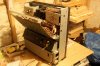
IMG_0895_2.jpg

Thanks...
 
Last edited:
Register to hide this ad
A friend of mine has a capstan motor if yours is fried.

Good to know, thanks. I might have to take up up on that.

I downloaded the TASCAM 34 Operation/Maintenance manual, but there is nothing there (as far as I see) to walk me through a test procedure for the capstan motor. I guess I'm going to have to use my own common sense. Should I just de-solder the lead wires and slowly apply DC voltage to see if it starts spinning (or generating too many amps)? A DC motor should also generate AC if I spin it by hand. I guess it can't hurt if I try that first.

Also, I see that the motor has 4 wires. Are two of the wires for slow speed and the other two for fast?

Thanks
 
Good to know, thanks. I might have to take up up on that.

Also, I see that the motor has 4 wires. Are two of the wires for slow speed and the other two for fast?

The two brown wires from the motor are the frequency generator connection for servo speed control.
 
The two brown wires from the motor are the frequency generator connection for servo speed control.
Thanks for this info.

I actually made some progress.

------------------------------------------------------------------------------------------------------------------
SOLVED:

The reel brake solenoid was stuck, which is why the takeup reel was only spinning for a second, when PLAY was pressed. Now it works OK.

------------------------------------------------------------------------------------------------------------------
DIAGNOSTICS:

Then I did some diagnostics around the capstan motor and found a few things that should help.

First, I now see that there is a pair of coax wires (red and white centers) in addition to the two brown wires, from the motor. Without de-soldering I connected a scope and found that one brown wire (the one not connected to ground) will show a sine wave when I turn the motor shaft. No other wire from the motor shows any life when I turn the shaft.

The white coax center wire shows 34.7VDC at all times, regardless of the tension arm. Other wires show 0V.

When I engage the tension arm these measurements do not change.

There are 8 wires connected to the small PCB to which the motor is connected. Those are labeled as follows:

+2
0
+1
P+
Sc
PR
H
L

the +2 is directly connected to the white coax center wire shows 34.7VDC at all times. Other connections show 0V when tension arm is off.
However, when tension arm is ON they all get somewhat less than 24VDC.

There are 3 transistors, one power transistor and one IC. The heat sinked power transistor D880 shows 0V when tension arm is ON.

------------------------------------------------------------------------------------------------------------------

Could any of these diagnostic steps shed any light on what might be wrong?

Thanks...
 
The motor could be toast. Not uncommon on these decks. Especially if the belt turned to mush and jammed the motor.

Simplest thing is to unsolder and apply 12v to the motor power wires. If it spins, the problem is on the control board, usually.
But of course, test all fuses and voltages.

Sam is a lot better with these decks than I am, maybe he'll chime in. The service manual would help a lot as to what voltages to expect where.
I had a Tascam 32 when I was 20.... geez, that was a long time ago.... had to replace the motor. It was toast. Nice deck, I made some
great recordings on it. The 34 is basically the same, just 4 tracks.

IF you do get the motor running, I strongly suggest cleaning and oiling it. These motors are NOT cheap!
 
Simplest thing is to unsolder and apply 12v to the motor power wires.
This is a test I was going to do but I want to be clear which wires to apply this voltage to.

So, not the brown wires. But then there's a pair of coax cables, one with a red center wire and one with a white center wire. I'm guessing the one with the red center wire is the one I should use. Is that correct?

Sam is a lot better with these decks than I am, maybe he'll chime in.

I sure hope he does chime in.

Thanks...
 
I'm not sure if this makes any sense, but my next step is to exchange the semiconductors, one by one, on the control PCB. There are only 6 semiconductors there, and all are very cheap.

2901N - .63c
D880 - .74c
C1815 - .22c
A1015 - .22c
C1627 - (obsolete)
a zener diode

I'll start by swapping the 2901N quad comparator and see what happens. Only two of the four channels are used, actually, and now I measure 11.9V on the output of one channel and only 0.2V on the output of the other. I also didn't see any wave forms on my scope, on that output, so there's a chance that there should be more than 0.2V there. I know I could have just rewired that suspect channel to one of the two free channels of the IC, but for .63c I didn't want to bother with jumpers.

If a new IC doesn't solve the issue I'll swap the transistors one by one and see what happens.

I don't know what to do about the C1627 transistor, but let's see what happens first.

I would still like to test the motor by applying 12VDC to it, but I was not lucky in getting a response to tell me which wires to use. If anyone that knows the answer picks up this thread, please let me know, as I'd like to perform this test.

Also, as you can see I'm just one step above a lay person when it comes to electronics, so if any of you see any technical reasons why I should not be swapping semiconductors, please let me know right away.

Thanks...
 
I would still like to test the motor by applying 12VDC to it, but I was not lucky in getting a response to tell me which wires to use. If anyone that knows the answer picks up this thread, please let me know, as I'd like to perform this test.
Thanks...

The two wires for motor power are the grey sheathed red and white wires. The brown wires are the frequency generator connection for speed control comparator.
 
The two wires for motor power are the grey sheathed red and white wires...

Thanks for this info.

At all times (regardless of tension arm) there is 34.7VDC going to shield and white wire. I do not measure any voltage between shield and red, even when I engage the tension arm. However the control board does get close to 24VDC on the connections, when I engage the tension arm.

Should I disconnect the red wire and apply 12VDC to it, to see if the motor spins?

Thanks....
 
Thanks for this info.

At all times (regardless of tension arm) there is 34.7VDC going to shield and white wire. I do not measure any voltage between shield and red, even when I engage the tension arm. However the control board does get close to 24VDC on the connections, when I engage the tension arm.

Should I disconnect the red wire and apply 12VDC to it, to see if the motor spins?

Thanks....

Voltage is applied between red and white
 
Thank you for the info.

I desoldered those wires from the control board. First measured continuity/resistance between red and white wires. I do not measure any continuity nor resistance.

I hooked them up to a variable DC power supply and slowly increased the voltage to 16V DC. Motor does not move. I also hooked up through amp meter and there is no current.

It could be just a connection in the motor, right? At this point I feel I have nothing to lose if I open the motor and look inside. But before I do that I wish to ask if there are any unexpected surprises, if I open that motor. Any spring loaded stuff that can't be put back together?

Thanks...
 
I opened up the motor and discovered that I wasn't the first one there, because there was one plastic washer that was already out of place. On the stator side there is one component that looks like it used to be a resistor, which is burned out.

Does anyone knows the value of this resistor (ohms and watts)?
IMG_0934.jpg


Thanks...
 
That’s not a resistor, it is an inductor and is probably one that is 10uH size made for 1 amp.
 
Thanks for the good info.

I'm concerned about what might be the reason why this overheated in the first place. Even if I install a new motor would it overheat?
 
You might have carbon from the motor brushes bridging sections of the commutator which causes a higher than normal current draw. Review this thread for additional details:

http://www.tapeheads.net/showthread.php?t=60058&highlight=inductor

Thank you for this link, dhnash. I read through that and followed the links from there, too.

My motor is definitely burned and I need to determine if I want to try rebuilding it. So far I know this:

1 - the inductor is burned.
2 - the electrolytic cap leaked (I would replace it with a film cap on the outside)
3 - the rubber reinforcements on the brushes melted
4 - the 7-terminal soldering ring, to which all the coils are soldered to is damaged
5 - three of the coils have burned wires (like blown fuses)
6 - there might be shorts within some coils, as I measure lower resistance
7 - the D880 transistor is dead (short between C and E pins)
8 - the contacts of the brushes do not show much wear

I measure the magnet wire to be .14mm, so I guess it must be 35-AWG wire. There are 7 coils and I guess I can count the number of turns as I unwind and replicate that as I rewind.

At this point I wouldn't mind getting some advice from anyone that might have attempted this kind of repair. How likely am I to succeed? I am quite good with precision work, so I believe I can rewind a rotor, patiently. Also, once the coils are wound, do I need a strobe to balance the rotor.

IMG_0938.jpg
 
Last edited:
A friend of mine has a capstan motor if yours is fried.

At this point I think I have to start considering this option.

Do you know how much is your friend asking for this motor, and does it come with the control board?

Thanks...
 
I do not, but can put you two in contact. Pm me your email in private and I’ll forward it.
Or you can contact him on tapeheads if you like.
 
Back
Top Bottom