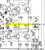
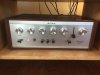
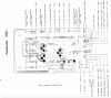
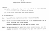
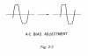
I am in the process of restoring a very nice Sony TA-1120A integrated amp, and I have questions about the procedure for setting the AC bias current. I'm comfortable setting bias on amps where values and test points are clearly stated. However, the instructions in the service manual require the use of an attenuator and an oscilloscope, both of which I have access to at a friend's shop (it's just a pain to get out there). I am wondering if there is a way to measure the bias current using my DMM just to make sure it's holding steady and within reason after I replace the old electrolytics. I think I need to measure across the emitter resistors, but I am not the best at schematics and would love some help and to learn in the process.
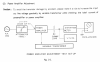
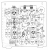
Here is a diagram of the driver boards.
Thanks.
Here is a diagram of the driver boards.
Thanks.
Last edited: