• The move to the new server is done. There are some software and database maintenance updates in process. This has us passing the hat around to help out. We appreciate any donations. Seriously, even a dollar helps. The payment page may be found here - https://www.audiokarma.org/support.html

Silvertone 528.59441 console amp

thorpej

AK Subscriber
Subscriber
I have this old Sears Silvertone 528.59441 console amp, from a Sears Silvertone model 70A console (AM/FM tuner, turntable, tape input, 1 external speaker for stereo). It was the listening device in my office for a spell, but was replaced by my Magnavox 8802, at which time the Silvertone took up residence in the garage.

Well, it finally gave up the ghost. Plays meekly for a bit and then slowly gets quieter and quieter. It's all original, unrestored (except for one replaced 12AX7 tube), and so it's time to give it an overhaul.

This evening, I poured myself a cocktail and went spent some time analyzing the schematic. The amplifier circuit consists of a 7025 AF amp stage, DC-coupled to a cathodyne phase inverter (the other triode in the same bottle). The output stage is 2 6V6s in push-pull, cathode biased, with a 6300 ohm plate-to-plate output transformer (8 ohm secondary). The output transformers are ... not big.

Did some quick math and it looks like it employs -11.5dB of feedback and has an input sensitivity of around 688mVrms (1.95Vpp). I'm guessing 10-ish W/ch is the output power.

I also have the pre-amp that goes with it ... it has a crappy little tone stack, loudness compensation on the tapped volume pot, a selector switch, and an RIAA phono EQ... but I'm probably going to ditch the pre-amp and just install simple volume pot on the amp chassis instead (it's just going to be fed by an AirPlay device anyway, and this let's me harvest the tubes from the pre-amp -- a 7025 and a 12AU7).

Seems like a nice little circuit. I like that they DC-coupled the first two stages. One change I plan to make along the way is to change the coupling caps between the PI and the output stage... the stock caps are .02uF, and the grid leaks of the output stage are 270K. That gives a -3dB cutoff of ~30Hz. Like I said, the output transformers aren't big, but I doubt I'll be pushing this amp to full power ... ever, so I'm likely to bump the coupling caps to .033uF to (hopefully) improve the bass response a little.

I'm thinking of converting it to EFB.

Anyone else care to make any suggestions based on their reading of the schematic? (Attached.)
 

Attachments

Register to hide this ad
Maybe up the capacitance on the second section, say parallel another 60uf onto it making 100 or so total there.

To bad they didn't wired the input tubes sections opposite from 123, 678 otherwise I'd suggest a 7247 an tweak the splitter resistors for a bit better drive. ;)
 
Maybe up the capacitance on the second section, say parallel another 60uf onto it making 100 or so total there.

To bad they didn't wired the input tubes sections opposite from 123, 678 otherwise I'd suggest a 7247 an tweak the splitter resistors for a bit better drive. ;)

Oh, yes, thanks for reminding me about the can cap! I'm planning to replace the original can with one of the AES / CE 40/40/40/40 @ 450 cans -- note how the reservoir cap is 60uF in the original schematic ... that exceeds the rating of the 5U4 by quite a bit (max 40uF), and the original rectifier tube did fail a couple of months ago ... I had almost forgotten about that. Yah, I'll go ahead and tack in some extra on that second section.

Hm, interesting suggestion about using a 12DW7 .. no loss of sensitivity because the low-mu section would be used for a cathodyne. ... 6, 7, 8 are section 1 of a 12DW7, which is the high-mu section, and those are the AF amp pins in the schematic... hm... I will consider this!
 
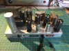
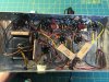
Snapped a couple of photos of the unit. It's pretty compact and kind of a mess underneath, but not horrible. I can put banana plugs directly into tags on the output transformers (see the third photo). The input cable from the pre-amp (using a proprietary connector) is going to be removed / repurposed for a pair of RCA jacks, and I'll put the EFB pot where the strain relief was. I'll probably mount the volume pot on the side of the chassis opposite the power transformer because there's some space in the underside there -- this thing is just meant to be mounted on a pine board in the garage anyway, so it doesn't have to be pretty :-)
 

Attachments

  • IMG_3098.jpg
    IMG_3098.jpg
    107.6 KB · Views: 127
  • IMG_3099.jpg
    IMG_3099.jpg
    127.4 KB · Views: 114
  • IMG_3102.jpg
    IMG_3102.jpg
    81 KB · Views: 113
Well, I seem to have miscalculated the input sensitivity.

I poked around at it last night and discovered what was making it play weakly (muffled, distorted sound) ... the solder tag on pin 8 of the rectifier socket was about to snap off, and in fact, broke wile I was poking around. I replaced the socket, and it now sounds as good as it ever did (since it's been in my possession, anyway). So, I jury-rigged a direct input from my iPod to the amplifier, and while it still sounds very good, it's not producing much output. I need to poke around at it a little more.

The second stage of the pre-amp (schematic attached) is a 12AU7, so not very high gain. Just enough to recover from the tone stack. Signal from the "tape" input of course bypasses all of the equalization stuff and goes straight to the loudness-compensating volume control. From there, into the 7025, which is grid-leak biased, and the grid sits at -0.9V. That feeds the tone stack, which then feeds the 12AU7 before going out to the amp chassis.

The naive math says the gain of the 7025 is 77, but I'm not sure I believe it (is it different for a grid leak-biased stage?). The math says the gain of the 12AU7 is 12.
 

Attachments

Nice little amp,,, specially the Schumacher OPTs... lots of ceramic caps, but you can fix that...

I guess the advantage of those ceramic caps is their longevity. Honestly, it's not a bad sounding little amp even with the ceramic caps. My biggest beef with it is the cut-off frequency used in coupling the output stage and the fact that the tone stack in the pre-amp's bass control is rather "boomy" as far as it's roll-off is concerned.
 
I still have some ceramic caps left in a Maggy 185, which sounds good also,,, just changed the PS and coupling caps to try it out...
This is a timely thread,,, I have been working on the RCA PA amp, and am finding the same low gain on the line stage problem as you are,,, Phono/line into a 6AU6 right before the tone stack, and a 12AU7 right after, with not enough output... I can feed a CDP, tape deck in one unused mic jack, modified for guitar input, and get lots of gain, no real distortion, but real boomy bass, with the bass pot turned up... Bass seems to really draw a lot of current, pegs a mA meter I had connected...
Looking fwd to any progress you make,,, Thinking of rewiring the 12AU7 to 12AX7 just to try...
May be too much for the guitar/mic stages, tho...
 
Ceramics in the feedback loop I would not bother changing anyway.

It's possible that I mis-calculated the gain of all of the stages in the power amp... or that I mis-calculated the amount of NFB. Since the first stage is un-bypassed, I could add a bypass cap and bump the gain a fair bit (from 60 to 78), but I'd have to adjust the feedback network (no biggie, but...) Note that after the -11.5dB feedback is applied, the gain of the first stage is really 15, rather than 60.
 
Honestly I figured out a while ago that I'm not smart or ambitious enough to calculate things, especially when I can just measure it in far less time.
 
Ok, put the Giants game on the 1929 Philco in the garage and sat down for some quality time with the scope. Set the input signal to the amp to 1Vpp. On one channel, I'm getting out 10Vpp on either output of the PI, which is pretty close to what I calculated (with either an original 7025 or a new JJ ECC83). On the other channel, I'm getting 1.28Vpp with an original 7025 or about 3Vpp with a brand-new JJ ECC83. I've swapped the original 7025s between each channel, and there is no change. The original tubes are a bit weaker than new ones, it seems, but there is definitely a problem with one of the channels. Time to go resistor hunting.
 
Ok, yah, the 270K plate resistors for the AF amp stages have WAY WAY WAY drifted. One reads 520K, the other reads 2M or so. Cathode resistors and grid stoppers are OK (a little off, but within specified tolerance). The 100K plate and cathode resistors on the PI are fine. The 1K grid stoppers on the 6V6s are OK, as are the 270K grid-leaks. The feedback resistors are also OK.

So, I think I've found the culprit. I don't have any 270Ks in my stash, but I have some on-order (along with a new can cap).
 
Well, for the one side that was reading > 2M ohm, I just went ahead and clipped in the 240K+33K in parallel, and sure enough it completely solved the gain + clipping problem on that channel. Output tubes are biased at -15V, and I was able to get 25Vpp out of the phase inverter before some visible distortion of the sine wave appeared on the scope, so I feel pretty confident about being able to get pretty close to pull power (like the Magnavox console amps, I assume this one is biased fairly cold, but I haven't measured the output stage's idle current yet).
 
Back
Top Bottom