• The move to the new server is done. There are some software and database maintenance updates in process. This has us passing the hat around to help out. We appreciate any donations. Seriously, even a dollar helps. The payment page may be found here - https://www.audiokarma.org/support.html

Silvertone 528.59441 console amp

Right, well, new 270K plate resistors on the 7025s fixed it right up. I'm listening to Grant Green on it right now. Curiously, one 7025 seems to draw more current than the other (about 17V additional drop across the 270K resistor), and it seems to follow the socket. I'm a little puzzled about that one. Cathode bias resistors check out OK, as do the grid leak and grid stoppers. For now I'm going to let it slide, as I can't spend any more time on it for a few days. But hey, progress! :-)
 
Just replaced the coupling caps -- the original .02uF ceramics have been replaced with .033uF film caps. Bass response seems better according to my completely subjective listening tests. The next step should probably be replacing the original can cap, but I think instead I will get the new input jacks and volume pot wire up as I'm not hearing any power supply noise to speak of at the moment.
 
Put in an EFB circuit tonight, slightly modified from @dcgillespie's 9302 version ... the divider network for the LM337 adjustment pin is 330K-(pot:10K)-18K, which gave me the adjustment voltage range I wanted for a nominal 290V screen voltage. I haven't dialed it in yet, but I set it up initially for 120mA across the 10 ohm 1% current sense resistor (so 30mA per tube, assuming matched tubes), which is cold. I'm guessing that it should probably idle at around 145mA total.

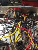
I was nice to get those clunky cathode bias resistors out of there.
 

Attachments

  • IMG_3133.JPG
    IMG_3133.JPG
    75.4 KB · Views: 22
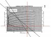
Drew up a quick load line analysis for the output stage at it's current operating point (300V on the plates minus the 20V EFB is supplying to the cathodes). Ignore the grid voltages as they're a little off -- the plate curves are for 250V screens, where as I have 270V (290V from supply - 20V cathode voltage) screens. The red line is the 30mA idle that they're sitting at now. I think I'm somewhat inclined to leave it at this operating point, or at least do a performance analysis of the amplifier at this first-guess starting point. The output tubes are also idling MUCH cooler than they used to.
 

Attachments

  • Load line analysis.jpg
    Load line analysis.jpg
    115.3 KB · Views: 12
Back
Top Bottom