To help promote transmitting tube amp builds, I am posting this in a stand alone thread because it may have been lost in the below thread on driver circuits.
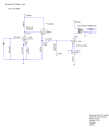
The Simple SE 845 circuit is intentionally designed to be simple, yet drive the 845 to full Class A1 operation without a complex expensive circuit. The power supply is more complex than the actual amp circuit, but it is fairly standardized and uses commonly available (inexpensive) components. It is also a fixed-bias design, which is something I do not usually do, preferring cathode-bias in almost all of my SE amps. Using fixed-bias helps preserve some of the plate voltage since we need about 105VDC of bias. This voltage can now be used for plate swing and turned into useful output power while keeping the main B+ under 1000VDC.
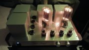
A Music Angel XDSE845 was used as the test mule for this amp circuit and power supply.
The main power transformer selected is an Edcor model XPWR314. Note that I have not actually bought or used this transformer, but based on its specs, should perform well for a stereo amp version with no problems. The XPWR314 power supply sections of the amp were confirmed with Duncan's Power Supply Design software. Additional power transformers will also need to be purchased for the various stages.
The biggest expense will be a good output transformer. Although not as popular as 2A3 or 300B OPT's, good 845 OPT are limited, but available. Be prepared to spend between $600~$1200USD for a good pair. Lundahl and Hashimoto come to mind, but there are others available as well. Be sure and choose a 10k primary impedance.
Resistors Rp1 & Rp2 may need to be increased/decreased depending on the final B+. You want this voltage to be between 860~880VDC. Main B+ voltages (A & B) are nominal values and may vary somewhat from the posted schematic. These voltages are easily measured with a standard meter since most all digital meters can easily handle 1000VDC.
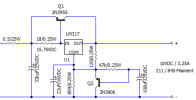
Resistors Rf1 & Rf2 may also need to be included if your 845 filament voltage is a bit high. increase or decrease these resistors in 0.1 Ohm increments until you reach a nominal 10VDC output.
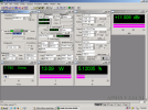
Full Power, 1kHz, 5% THD+N, 8 Ohm
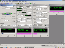
20kHz Full Power, 8 Ohm
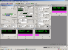
1kHz, 1W, 8 Ohm
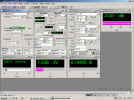
40Hz, 1W, 8 Ohm
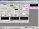
20kHz, 1W, 8 Ohm
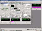
Frequency Response Sweep (Teal), Distortion (Yellow), 1W, 8 Ohm

40Hz, Full Power, 8 Ohm
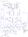
Power Supply
Transmitting Tube Driver Circuits - 211 / 845
@AlexHempel is designing an amp around a 845 and I wanted to explore different opinions on driver circuits. The challenge with driving the 845 is the voltage swing for Class A1 operation not to mention A2 operation. The Miller capacitance is not any worse than a 2A3 or 300B so it's strictly a...
audiokarma.org
The Simple SE 845 circuit is intentionally designed to be simple, yet drive the 845 to full Class A1 operation without a complex expensive circuit. The power supply is more complex than the actual amp circuit, but it is fairly standardized and uses commonly available (inexpensive) components. It is also a fixed-bias design, which is something I do not usually do, preferring cathode-bias in almost all of my SE amps. Using fixed-bias helps preserve some of the plate voltage since we need about 105VDC of bias. This voltage can now be used for plate swing and turned into useful output power while keeping the main B+ under 1000VDC.
A Music Angel XDSE845 was used as the test mule for this amp circuit and power supply.
The main power transformer selected is an Edcor model XPWR314. Note that I have not actually bought or used this transformer, but based on its specs, should perform well for a stereo amp version with no problems. The XPWR314 power supply sections of the amp were confirmed with Duncan's Power Supply Design software. Additional power transformers will also need to be purchased for the various stages.
The biggest expense will be a good output transformer. Although not as popular as 2A3 or 300B OPT's, good 845 OPT are limited, but available. Be prepared to spend between $600~$1200USD for a good pair. Lundahl and Hashimoto come to mind, but there are others available as well. Be sure and choose a 10k primary impedance.
Resistors Rp1 & Rp2 may need to be increased/decreased depending on the final B+. You want this voltage to be between 860~880VDC. Main B+ voltages (A & B) are nominal values and may vary somewhat from the posted schematic. These voltages are easily measured with a standard meter since most all digital meters can easily handle 1000VDC.
Resistors Rf1 & Rf2 may also need to be included if your 845 filament voltage is a bit high. increase or decrease these resistors in 0.1 Ohm increments until you reach a nominal 10VDC output.
Full Power, 1kHz, 5% THD+N, 8 Ohm
20kHz Full Power, 8 Ohm
1kHz, 1W, 8 Ohm
40Hz, 1W, 8 Ohm
20kHz, 1W, 8 Ohm
Frequency Response Sweep (Teal), Distortion (Yellow), 1W, 8 Ohm
40Hz, Full Power, 8 Ohm
Power Supply
Last edited: