• The move to the new server is done. There are some software and database maintenance updates in process. This has us passing the hat around to help out. We appreciate any donations. Seriously, even a dollar helps. The payment page may be found here - https://www.audiokarma.org/support.html

Smoking, Solder Melting Diodes

MikeWSeattle

New Member
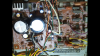
I've got a Marantz 1530 that is giving me problems. I picked it up at a screaming deal and did my typical LED light swap, found some replacement knobs and cleaned with alcohol/Deoxit. After a few hours of enjoyment the unit began smoking a bit and would no longer play sound .

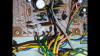
Upon opening it up I noticed that the Q801 and Q802 three leg diodes (DS133B) had melted together. Further research led me down the path of replacing this NLA part with 2x 1N4007's back-to-back. I figured it wouldn't hurt to do a recap so I did that as well. The first test run led to the Q805 transistor (2DS313E) sparking which I replaced with a MJE15032G that I found cross referenced here.

I would be happily listening to an album rather than posting here if I wasn't back to square 1 with the original culprit causing havoc. The looped 1N4007's are still smoking and causing the solder to melt.

Is there something I should further test or something I am doing wrong that could be causing this? I am not making and claims to electrical engineering expertise, but I am reasonably proficient with a multimeter.
Screenshot_20180206-230525.png Screenshot_20180206-230507.png
 
Register to hide this ad
Not sure I have ever seen solder melt before a component goes up in smoke.....

Why not post a snippet of the schematic?

Also the component layout view.... Are those main filter caps installed correctly?
 
Last edited:
Not sure I have ever seen solder melt before a component goes up in smoke.....

Why not post a snippet of the schematic?

Also the component layout view.... Are those main filter caps installed correctly?

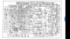
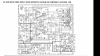
Here is the schematic and layout. The main filter caps were originally 3x legged, but it looked like one was just for support as it didn't seem to go anywhere on the board.
Screenshot_20180207-063513.png
Screenshot_20180207-063508.png
 
Schematic looks to me like the center legs make connections. I have seen other threads where DS133B's were made from 1N4007's, but they made three legs out of it. Hopefully someone who knows better than me will chime in, but I think you need that center leg.
 
Invariably, when something smokes, it's not the cause of the problem. It smoked because too much current went through it, so follow the possible paths that could allow that. It could be a component, but could also be a short on a trace or wire. Once the diodes have gotten hot enough to melt solder, they may test OK, but I'd never reuse them. I'd also check the main bridge for bad diodes. It seems like that would blow a fuse or filter cap, but maybe not.
 
I have seen power resistors get so hot they melted the solder and the part fell out of the board as it was mounted component side down. Kind of a protection scheme! Also I've seen the vitreous resistors (ceramic looking) get so hot they were cherry red. This was in professional instrumentation.

I agree with Conrad (of course!) on the possibilities. I'd be looking at whatever filter caps were after those diodes.

A nice replacement for the dual diodes are the MUR1620CTG or CTRG depending on the polarity of the original part, common cathode or common anode.
 
A nice replacement for the dual diodes are the MUR1620CTG or CTRG depending on the polarity of the original part, common cathode or common anode.

Wish those would work but the DS133B is 2 diodes in series. Just replaced one on a 1090 and had to make it with 2x4007’s.
 
Three legs. I crafted the center leg so the two diodes were twisted and soldered on the top section but the bottom only had one lead so as to fit in the original hole. Took a few minutes of fussy work to get it just right but worked great.
 
To isolation the issue.... Disconnect the amp and preamp from the power supply and test....

The diodes don't over head , trying reconnecting the amps one at a time... L/R power and preamp all separately....

Now that might not be easy on that thing....

Or use an IR thermometer to find when the power is going....

Jk
 
To isolation the issue.... Disconnect the amp and preamp from the power supply and test....

The diodes don't over head , trying reconnecting the amps one at a time... L/R power and preamp all separately....

Now that might not be easy on that thing....

Or use an IR thermometer to find when the power is going....

Jk

Thanks I'll give that a try and report back.

Is it possible that the zener on that board is causing the issue? I pulled it and it tested fine without any power applied to it. Unfortunately I don't have a way to test it under load.
 
Wish those would work but the DS133B is 2 diodes in series. Just replaced one on a 1090 and had to make it with 2x4007’s.
Thanks Mike B for making that clear. I'm thinking of the "131" and "132" types like those that are in a 2325.

Yes Mike WS, it could be the zener. Can you use micrograbber leads hooked across the diode and get a voltage reading while briefly powering on? Other wise it takes an external power supply capable of more than the rated zener voltage and a current limiting resistor like around 1K to test the zenering voltage.

Also to be mentioned is the technician's friend, the dim bulb tester AKA "DBT". Search around for it if you don't have one. Basically it is inserting an incandescent (but not LED) light bulb in series with one lead of the mains power. Never jury rig such a device!
 
Maybe you can re verify the installation of the filter caps?

A quick web search shows a picture of the 1530, notice the clocking of the filter caps. The negative stripes are very close to each other.

index.php


On yours they are off slightly.

index.php


I am not sure if this is the problem, your new caps may have wrapping that is slightly off. I doubt you would be able to run for a while if they were installed wrong.

SInce your original problem was related to the back to back diodes I would check J817 (32V) and J818 (12V) to see if one of them was shorted to ground. Both of these load the section of the power supply that is having a problem. Either the load is too much or something in the section around Q805,Q806,Q807 is bad. You may need to disconnect J817 and J818 to get a proper reading. Check the wire to ground.
 
Maybe you can re verify the installation of the filter caps?

A quick web search shows a picture of the 1530, notice the clocking of the filter caps. The negative stripes are very close to each other.

index.php


On yours they are off slightly.

index.php


I am not sure if this is the problem, your new caps may have wrapping that is slightly off. I doubt you would be able to run for a while if they were installed wrong.

SInce your original problem was related to the back to back diodes I would check J817 (32V) and J818 (12V) to see if one of them was shorted to ground. Both of these load the section of the power supply that is having a problem. Either the load is too much or something in the section around Q805,Q806,Q807 is bad. You may need to disconnect J817 and J818 to get a proper reading. Check the wire to ground.

On the advice of jstang, I got after it with the IR gun and found that J813 was getting instantly hot and the components in the section you mentioned were not showing any voltage. I had replaced Q805 because it was sparking when I first replaced the caps, so I will go retest the new one to make sure it was the right part. Somewhere I had cross referenced it to a MJE15032G.

Regarding the orientation of the main caps, I switched back to the old ones which are 3 pin caps .I thought the 3rd leg was just for structural support, but found after testing that it seems to serve some function. Looking at the board, it appeared to have a trace to nowhere.

Once I test out Q805 and get power to Q806/Q807 I'll report back.

Would this section lead the the J813 overheating? It is the post that has a Grey wire going back to the transformer.
 
Maybe you can re verify the installation of the filter caps?

A quick web search shows a picture of the 1530, notice the clocking of the filter caps. The negative stripes are very close to each other.

index.php


On yours they are off slightly.

index.php


I am not sure if this is the problem, your new caps may have wrapping that is slightly off. I doubt you would be able to run for a while if they were installed wrong.

SInce your original problem was related to the back to back diodes I would check J817 (32V) and J818 (12V) to see if one of them was shorted to ground. Both of these load the section of the power supply that is having a problem. Either the load is too much or something in the section around Q805,Q806,Q807 is bad. You may need to disconnect J817 and J818 to get a proper reading. Check the wire to ground.

I was testing the section you had mentioned and found that there was no power getting to the J817 (32V) and J818 (12V) test points so I turned my attention to the power transistor Q805 as it seemed to be the culprit blocking the power to the section. Should the center leg (collector) be electrically conductive to the heat sink (which in turn grounds to the chassis)? Does that matter? It definitely is right now and I went to battle with the thermal grease to create a non-electrically conductive buffer to without success. The screw on the transistor has a rubber piece leading me to believe that it should not electrically conduct, but I wanted to make sure before going out and buying some thicker grease.
 
I was testing the section you had mentioned and found that there was no power getting to the J817 (32V) and J818 (12V) test points so I turned my attention to the power transistor Q805 as it seemed to be the culprit blocking the power to the section. Should the center leg (collector) be electrically conductive to the heat sink (which in turn grounds to the chassis)? Does that matter? It definitely is right now and I went to battle with the thermal grease to create a non-electrically conductive buffer to without success. The screw on the transistor has a rubber piece leading me to believe that it should not electrically conduct, but I wanted to make sure before going out and buying some thicker grease.

I think you have just discovered your problem. Q805's collector should be at 50V, not ground. You need an insulator between the transistor and heat sink along with the proper screw and insulating washer. Make sure that your not using conductive grease, the kind you might find for a microprocessor heat sink.

Something like this:

shopping
 
Sorry.. I forgot to mention the metal tab of the transistor can be electrically connected to the collector, this is normal. In your case the collector is being grounded through the heat sink because the insulator is missing.
 
You could use the MJF15030. It's all plastic and insulated so it can't short out.

Thanks a ton for the detailed responses. I am going to find myself an insulator for now and remember that all plastic part for the future. I'll report back with the results.
 
Back
Top Bottom