• The move to the new server is done. There are some software and database maintenance updates in process. This has us passing the hat around to help out. We appreciate any donations. Seriously, even a dollar helps. The payment page may be found here - https://www.audiokarma.org/support.html

Someday soon, my Silvertone 1484 will live again ... a long-form thread.

thorpej

AK Subscriber
Subscriber
Howdy folks... it's been a while!

For various and sundry reasons[*], I have a lot of unfinished projects, and I'm trying to make a concerted effort to ... finish some of them! I know, right??

[*] Nothing terribly serious, mind you... just life + the usual shiny-object-distractions that are irresistible to the average ADHD-afflicted individual such as myself.

One of them is my Silvertone 1484 amp head. I literally dug this out of a dumpster in the rain when I was in college in the early 90s, and managed to not electrocute myself in an effort to make it go... and it survived its fair share of terrible punk rock gigs where the band was paid in bottomless red cups of tasty Pacific Northwest craft beer.

Fast forward to ... several years ago, I took it upon myself properly restore the darn thing. I cobbled together sufficient woodworking skills to build a new speaker cabinet and case for the amp head it self (and covered it in black Tolex). I got it limping along again electrically, but at the time, it had to get back-burnered due to other obligations, it got put into cold storage, and then sat... until...

Fast forward to 2 weeks ago, my wife and I are making a concerted effort to purge no-longer-needed stuff in cold storage. I reassured my wife that I still very much need this amplifier, and that I will make a concerted effort to get it where I want it to be so that it is at least a useful waste of space. I will have to brighten up some of the hardware, of course, but I absolutely need to undertake a full electrical restoration of the unit. These things are already problematic vis a vis noise, and the tremolo wasn't wasn't working when I stashed it away, so I decided that a full rebuild is warranted. These amps are fairly desirable because Danelectro's short-cuts made them sound so good, but this particular example is already non-original in many ways, so I'm not killing any value by doing so.

One of the things I've been distracted by the last several years is improving my PCB layout skills (mostly in the digital/retrocomputing realm; I'm a software guy who's fully self-taught in the hardware realm), so I decided that rather than doing everything p2p, I'll recreate the original circuit on a PCB, using flying leads to the tubes, pots, and switches. I don't intend to make any meaningful changes to the original circuit at all. Here are the mods that I intend to make:
  • Power supply will use 1N4007 diodes everywhere because there's no reason not to.
  • The caps in the stacked voltage doubler B+ supply each get bleeder resistors.
  • The output tubes each get 2K2 grid stoppers and 470R screen resistors for protection.
  • The input stage will get grid stoppers, as well, (to tamp down noise) but I haven't settled on a value yet.
Everything else -- bone stock. Even the extremely stupid stuff, like how the wet signal from the utterly terrible reverb "tank" is injected into output. (That particular bit of the circuit is absolutely diabolical, but pennies must be saved when you're producing in volume, I guess...). And yes, even the clever-but-crappy power supply that leverages lower-voltage-rated caps because of their extreme surplus abundance in the post-AA5 radio era. There is a copy of the original manual with a ... recreated? schematic that's been circulating for years that I'm working off of. There is one mistake in it that I've found (a missing junction dot in the cathodyne phase splitter), but other than that seems true to my unit thus far.

When I'm finished getting the circuits drawn in the schematic that will be used to fab the PCB, I plan to make all of the component references match this widely-circulated schematic for easy reference.

Anyway, in this thread, I plan to chronicle my progress through the re-creation process, describe my design approach, and provide commentary on the individual parts of the 1484 schematic as I work on them. (Ok, well, I've actually done a few stages already, so the first few posts will be a sort of retrospective.) I'll be putting my meager artwork skills to the test as I crop-and-annotate bits of the original schematic for this thread, so please be patient with me. Follow the thread if you're interested and hopefully I'll be able to provide a bit of entertainment for y'all as I chip away at this wonderful little object.

Cheers!
 
Register to hide this ad
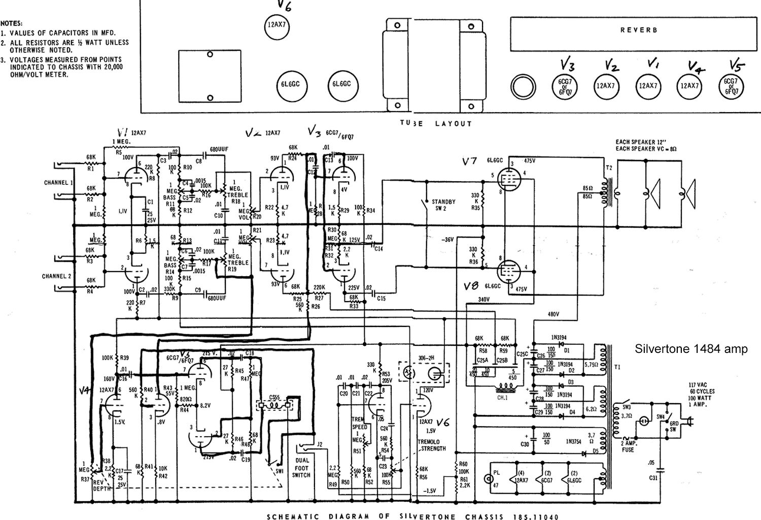
What tubes are used, and could you post a schematic?

Dōmo arigatōgozaimasu!
Input stage: 12AX7 (1/2 per channel)
Gain stage after tone controls: 12AX7 (1/2 per channel)
<both channels are mixed together here>
Gain stage after mixing + cathodyne phase splitter: 6CG7 / 6FQ7
Output stage: push-pull 6L6GC, fixed bias

Applicable to channel 2 only:
Reverb stage uses 12AX7 (amplification) + 6CG7 / 6FQ7 (driver duty).
Tremolo circuit uses 12AX7 for the oscillator.

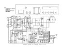
Full in-circulation reproduction schematic I mentioned attached.
 

Attachments

  • Sears_Silvertone_1484_Twin_Twelve_REPRODUCTION_Schematic.jpg
    Sears_Silvertone_1484_Twin_Twelve_REPRODUCTION_Schematic.jpg
    154.2 KB · Views: 8
b7dc759b-3d1f-446c-b7bc-2feed342509a.jpg

Found this schematic on the Net. Someone made annotations in the Reverb and phase inverter sections. By chance, do you have the mating cab?

Double-click on the image to enlarge it.

Good luck with the project!

:thumbsup:
 
Found this schematic on the Net. Someone made annotations in the Reverb and phase inverter sections. By chance, do you have the mating cab?

I never had the original speaker cabinet. Back in the "s***y punk rock band" days, I used a single-10 hand-build cab that was objectively terrible but did the job. I currently have a pretty nice hand-built Tolex-covered dual-12 cab (in Fender blackface style) with a 100W L-pad attenuator so I can avoid making the neighbors upset.
 
I never had the original speaker cabinet. Back in the "s***y punk rock band" days, I used a single-10 hand-build cab that was objectively terrible but did the job. I currently have a pretty nice hand-built Tolex-covered dual-12 cab (in Fender blackface style) with a 100W L-pad attenuator so I can avoid making the neighbors upset.
If you don't mind me asking, what speakers are loaded in the cab?

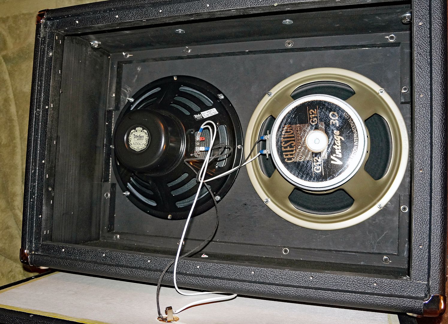
I DIY'd a 2x12 for my Bassman. One Alnico Weber and one Celestion Vintage 30 ceramic. A pretty unique tone.

98942296-1d33-4404-a6d3-874468b2b4f8.jpg
 
If you don't mind me asking, what speakers are loaded in the cab?

I DIY'd a 2x12 for my Bassman. One Alnico Weber and one Celestion Vintage 30 ceramic. A pretty unique tone.

98942296-1d33-4404-a6d3-874468b2b4f8.jpg

That’s music to my ears. Nice stuff.
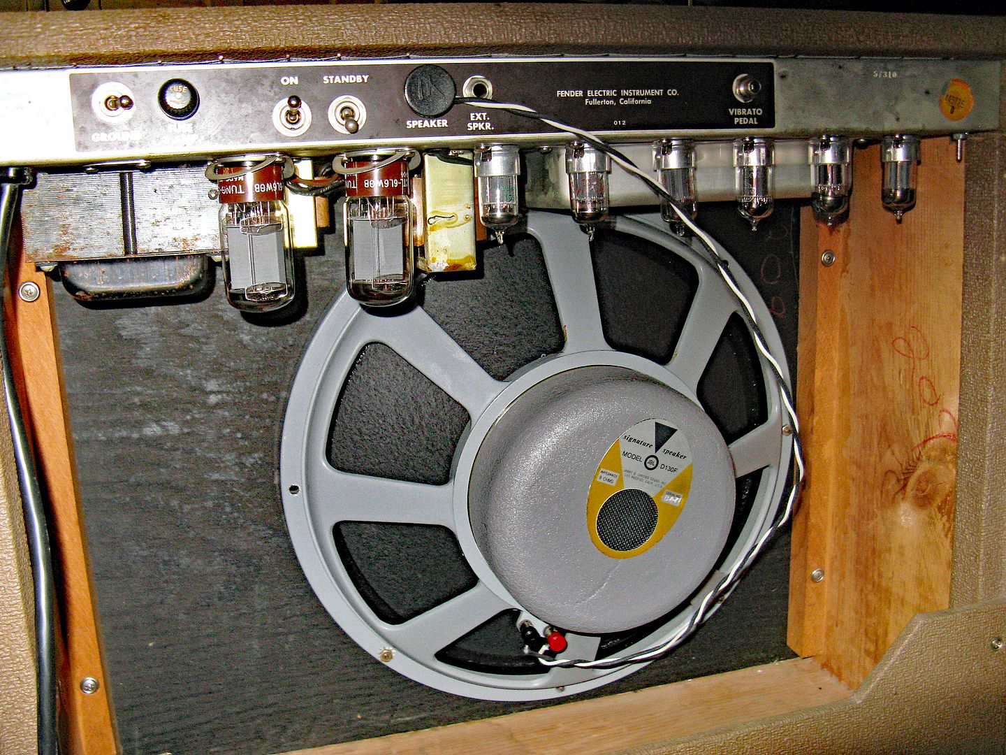
Another interesting set-up to use with the Silvertone is a speaker fitted with a single 15-inch JBL D130F driver. From time to time, speakers fitted with two reconditioned D130F drivers can be found on the second-hand market.
 
That’s music to my ears. Nice stuff.
Another interesting set-up to use with the Silvertone is a speaker fitted with a single 15-inch JBL D130F driver. From time to time, speakers fitted with two reconditioned D130F drivers can be found on the second-hand market.
The D130F is one of my favorite speakers. I've found a few over the years (a perfect pair from Australia!). Most needed to be re-coned. But if done by a pro, they can last another 50 years.

In my opinion, the 15-inch D130F has a much smoother, warmer midrange (especially in Fender amps) than the 12-inch D120F.

a2c50179-181b-4a23-bbce-21d3d820045a.jpg

D130F in a 1962 brownface Pro.

:)
 
Howdy folks... it's been a while!

For various and sundry reasons[*], I have a lot of unfinished projects, and I'm trying to make a concerted effort to ... finish some of them! I know, right??

[*] Nothing terribly serious, mind you... just life + the usual shiny-object-distractions that are irresistible to the average ADHD-afflicted individual such as myself.

One of them is my Silvertone 1484 amp head. I literally dug this out of a dumpster in the rain when I was in college in the early 90s, and managed to not electrocute myself in an effort to make it go... and it survived its fair share of terrible punk rock gigs where the band was paid in bottomless red cups of tasty Pacific Northwest craft beer.

Fast forward to ... several years ago, I took it upon myself properly restore the darn thing. I cobbled together sufficient woodworking skills to build a new speaker cabinet and case for the amp head it self (and covered it in black Tolex). I got it limping along again electrically, but at the time, it had to get back-burnered due to other obligations, it got put into cold storage, and then sat... until...

Fast forward to 2 weeks ago, my wife and I are making a concerted effort to purge no-longer-needed stuff in cold storage. I reassured my wife that I still very much need this amplifier, and that I will make a concerted effort to get it where I want it to be so that it is at least a useful waste of space. I will have to brighten up some of the hardware, of course, but I absolutely need to undertake a full electrical restoration of the unit. These things are already problematic vis a vis noise, and the tremolo wasn't wasn't working when I stashed it away, so I decided that a full rebuild is warranted. These amps are fairly desirable because Danelectro's short-cuts made them sound so good, but this particular example is already non-original in many ways, so I'm not killing any value by doing so.

One of the things I've been distracted by the last several years is improving my PCB layout skills (mostly in the digital/retrocomputing realm; I'm a software guy who's fully self-taught in the hardware realm), so I decided that rather than doing everything p2p, I'll recreate the original circuit on a PCB, using flying leads to the tubes, pots, and switches. I don't intend to make any meaningful changes to the original circuit at all. Here are the mods that I intend to make:
  • Power supply will use 1N4007 diodes everywhere because there's no reason not to.
  • The caps in the stacked voltage doubler B+ supply each get bleeder resistors.
  • The output tubes each get 2K2 grid stoppers and 470R screen resistors for protection.
  • The input stage will get grid stoppers, as well, (to tamp down noise) but I haven't settled on a value yet.
Everything else -- bone stock. Even the extremely stupid stuff, like how the wet signal from the utterly terrible reverb "tank" is injected into output. (That particular bit of the circuit is absolutely diabolical, but pennies must be saved when you're producing in volume, I guess...). And yes, even the clever-but-crappy power supply that leverages lower-voltage-rated caps because of their extreme surplus abundance in the post-AA5 radio era. There is a copy of the original manual with a ... recreated? schematic that's been circulating for years that I'm working off of. There is one mistake in it that I've found (a missing junction dot in the cathodyne phase splitter), but other than that seems true to my unit thus far.

When I'm finished getting the circuits drawn in the schematic that will be used to fab the PCB, I plan to make all of the component references match this widely-circulated schematic for easy reference.

Anyway, in this thread, I plan to chronicle my progress through the re-creation process, describe my design approach, and provide commentary on the individual parts of the 1484 schematic as I work on them. (Ok, well, I've actually done a few stages already, so the first few posts will be a sort of retrospective.) I'll be putting my meager artwork skills to the test as I crop-and-annotate bits of the original schematic for this thread, so please be patient with me. Follow the thread if you're interested and hopefully I'll be able to provide a bit of entertainment for y'all as I chip away at this wonderful little object.

Cheers!
Have fun. Please do let us know how you’re getting on.
 
The D130F is one of my favorite speakers. I've found a few over the years (a perfect pair from Australia!). Most needed to be re-coned. But if done by a pro, they can last another 50 years.

In my opinion, the 15-inch D130F has a much smoother, warmer midrange (especially in Fender amps) than the 12-inch D120F.

a2c50179-181b-4a23-bbce-21d3d820045a.jpg

D130F in a 1962 brownface Pro.

:)
That’s the mighty D130F.
 
If you don't mind me asking, what speakers are loaded in the cab?

I DIY'd a 2x12 for my Bassman. One Alnico Weber and one Celestion Vintage 30 ceramic. A pretty unique tone.

98942296-1d33-4404-a6d3-874468b2b4f8.jpg
i did something similar with my
4x12–L side 25w greenbacks, R side…,cant remember, each side
16r, each side with its own input jack. still very happy with it after 30 years.
 
Last edited:
The Power Supply

Power_Supply_annotated.jpg
This is the power supply of the 1484. It provides SIX (count 'em!) power rails:
  • B+1 - output tube plate voltage, nominally 480V as per the schematic (the schematic notes it drops to 475V after passing through the output transformer)
  • B+2 - output tube screens, nominally 340V, 3rd gain stage & phase splitter, reverb driver, tremolo oscillator
  • B+3 - 2nd gain stage (after tone and volume controls)
  • B+4 - 1st gain stage, reverb recovery amplifier, tremolo oscillator
  • C-1 - output tube bias, nominally -36V
  • C-2 - tremolo oscillator bias
Note the interesting topology of the B+ supply: it consists of two full-wave voltage doublers. The "high voltage" secondary windings are each only 91Vac, which rectifies to ~128Vdc, which is the maximum voltage each capacitor in the stack will see, allowing less expensive/bulky components to be used (lower voltage diodes and capacitors). Each winding's voltage doubler produces ~256Vdc, and since there are two stacked together, this produces an unloaded max voltage of ~512Vdc. Because each winding has its own voltage doubler that outputs DC, one need not be concerned about matching the phases of the PT secondary windings during construction. The output of this dual-stacked voltage doubler arrangement is the B+1 rail.

Note also the convenient tap for the B+2 rail: at the junction between C26 and C27, the a filter choke is connected, which feeds C25A to create the B+2 rail. The B+3 and B+4 rails are derived from B+2 using garden-variety RC filters on the capacitor can.

An interesting property of the design is it's remarkably low reservoir capacity for a 6L6GC push-pull design: just 25uF overall. This produces quite a bit of sag when the amp is being driven hard, which is a major contributor to the signature sound of this amplifier.

The C- supply is bog standard. Half-wave rectifier producing the output tube bias voltage, with an additional tap providing -1.5V to bias one half of the 12AX7 used in the tremolo oscillator.

In my rebuild, I'm using jellybean 1N4007 diodes (because I have a bag with probably 200 of them in my parts inventory), and 160Vdc radial caps in the voltage doublers for compactness. I'll not be using the can capacitor, instead opting for long-life axial 450Vdc electrolytics on the PCB (the can will remain for aesthetic purposes). One change I've made here is using a 10uF cap for B+4 rather than the 5uF in the original; this is for BoM simplification and noise reduction purposes. I've provisioned 220K bleeders on the voltage doubler caps (they're not needed for balancing) as a safety measure.

I'm using different nets for power supply ground vs signal ground; they'll get connected together eventually using a 0R resistor. This allows me to have different design constraints for the high current power supply ground traces vs the lower current small signal ground traces. Of course, high voltage also means more clearance between traces, and the use of top vs bottom side of the board for traces in the power supply is largely dictated by clearance rules.

Here's what it looks like in the PCB layout tool:

Screenshot 2026-10-14 at 4.38.48 AM.png

Apologies for the weird references for the 3 axial electrolytics -- this is a KiCad quirk, which only lets multi-unit devices have references that end in a letter.

Top renders with and without components:

Screenshot 2026-10-14 at 4.44.14 AM.pngScreenshot 2026-10-14 at 4.43.58 AM.png

Overall, the power supply section is quite compact -- approximately 5" x 2.5".
 
The Output Section

The output section is pretty normal. Starting on the left, we have a 6CG7 acting as the driver stage. The upper triode is a gain stage and the lower triode is a cathodyne phase splitter, both built in the simplest way possible. The gain stage is necessary because a cathodyne phase splitter has a gain < 1 (usually around 0.9; sorry, I'm not going to do the math to calculate it as built here :cool:), but considering the 6CG7 is a low-mu tube and lack of a bypass cap on cathode, the overall voltage gain here isn't going to be terribly high -- maybe roughly 13 after phase splitting?
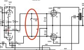
Note the error in the "original" reproduction schematic -- the junction dot where the 3 resistors meet in the lower triode (phase splitter) is missing. I've added one in red here.

Also note how the standby switch is implemented in the 1484. In classical Fender amplifiers, standby switched the main B+ rail, the intention being to prevent over-voltage on the power supply caps while the tubes are still non-conducting during warm-up. Unfortunately, this isn't great for the tubes or for the switch. If left in standby for too long, the tubes in a Fender amp will be subject to cathode poisoning, and having high voltage present on the switch pretty much guarantees arcing inside the switch when coming out of standby, thus shortening the life of the switch.

The 1484's standby switch is completely different, and is designed merely to mute the output stage. It does this by shorting the two output phases together, cancelling them out. Because of the power supply's design, it's not possible for the caps to experience an over-voltage situation during warm-up, so there's no need to protect against it. I suppose another nifty little side effect is that the standby switch can be used to check if your phase splitter is running out of balance :).

The output is a push-pull pair of 6L6GCs, Va=475V, Vg2=340V, Vg1=-36V, which should be roughly 26mA of quiescent plate current and around 12.5W of quiescent plate dissipation. Danelectro biased these tubes on the cool side for sure. The bias is not adjustable, and I don't intend to add any adjustment capability. Again, my goal is to run this amp is it would have run from the factory.

The output transformer has a 7.6K primary and a 4 ohm secondary. The OT is fairly under-sized, and saturates when the amp is being driven hard. I assure you, this is part of the charm of these amps.

Output_annotated.jpg
 
The Output Section

The 1484's standby switch is completely different, and is designed merely to mute the output stage. It does this by shorting the two output phases together, cancelling them out. Because of the power supply's design, it's not possible for the caps to experience an over-voltage situation during warm-up, so there's no need to protect against it. I suppose another nifty little side effect is that the standby switch can be used to check if your phase splitter is running out of balance :).

The output is a push-pull pair of 6L6GCs, Va=475V, Vg2=340V, Vg1=-36V, which should be roughly 26mA of quiescent plate current and around 12.5W of quiescent plate dissipation. Danelectro biased these tubes on the cool side for sure. The bias is not adjustable, and I don't intend to add any adjustment capability. Again, my goal is to run this amp is it would have run from the factory.

The output transformer has a 7.6K primary and a 4 ohm secondary. The OT is fairly under-sized, and saturates when the amp is being driven hard. I assure you, this is part of the charm of these amps.
Interesting standby switch!

Just put in the grid stoppers and screen resistors on the 6L6GC, check the nominal voltages, and I think that you'll be good to go.

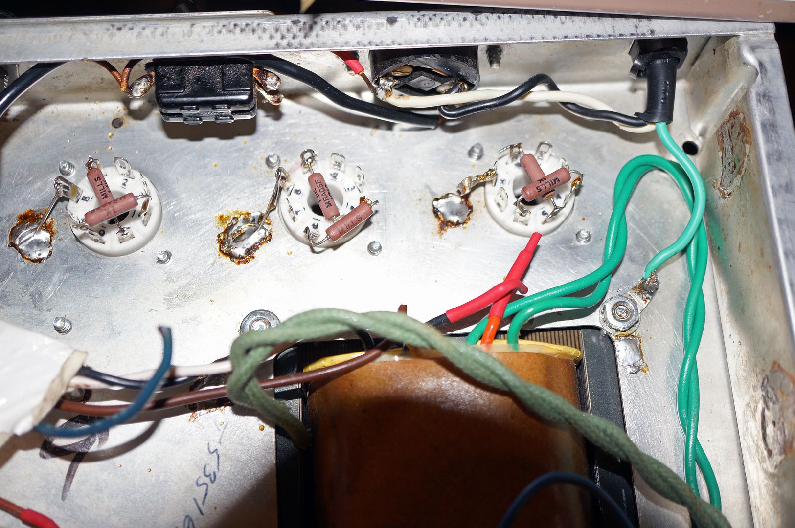
BTW... I'm sure you already know this. But Fender put those resistors on the tube socket to minimize lead length (and potential inductance-induced instabilities). Choose ones that have good heat resistance.

382f7764-18ae-4e73-aae6-cc0cdaed0181.jpg


Mills wire-wound resistors have good heat resistance and low inductance. Grid-stopper resistors are soldered across unused pin #1 and control grid #5. Screen resistors across #4 and unused #6. Then solder the input signal to #1. And the screen voltage tap to #6.
 
Last edited:
Here's what all of that looks like on the PCB.

Screenshot 2026-10-17 at 8.46.48 AM.png

I haven't routed the B+ or bias traces yet because I haven't finalized the exact location of this block on the PCB. I'm using WIMA MKP-series polypropylene film caps due to their compact footprint. And YAGEO MFR-series resistors that use the DIN0207 footprint -- a very compact 6.3mm long, 2.5mm diameter, 1/2W metal film.
 
Here's what all of that looks like on the PCB.

View attachment 3858313

I haven't routed the B+ or bias traces yet because I haven't finalized the exact location of this block on the PCB. I'm using WIMA MKP-series polypropylene film caps due to their compact footprint. And YAGEO MFR-series resistors that use the DIN0207 footprint -- a very compact 6.3mm long, 2.5mm diameter, 1/2W metal film.
There don't seem to be grid stoppers or screen resistors on that PCB for V7 and V8.

Thanks!
 
Here's what all of that looks like on the PCB.

View attachment 3858313

I haven't routed the B+ or bias traces yet because I haven't finalized the exact location of this block on the PCB. I'm using WIMA MKP-series polypropylene film caps due to their compact footprint. And YAGEO MFR-series resistors that use the DIN0207 footprint -- a very compact 6.3mm long, 2.5mm diameter, 1/2W metal film.

An interesting development – thanks for keeping us in the loop.
Unless you want to keep the original power transformer, wouldn’t it be simpler to opt for a conventional power supply given that you’re planning to rebuild this amplifier?

I can understand the use of a voltage doubler in an amplifier with a B+ voltage exceeding 500V DC, but in the case of the 1484, the voltages are within reasonable limits.

I have the original PT, and it is in good working order, so I see no reason not to use it. Besides, the behavior of the power supply is a factor in the way these amps sound, so I'd rather keep it original rather than attempt to replicate it.
 
Back
Top Bottom