• The move to the new server is done. There are some software and database maintenance updates in process. This has us passing the hat around to help out. We appreciate any donations. Seriously, even a dollar helps. The payment page may be found here - https://www.audiokarma.org/support.html

SONY 5650 Vfet amp advise before I start

gummy

Active Member
Hi,
I have a Sony 5650 Vfet amp that has died on me, so I am about to embark on a refurbishment, replacing transistors and caps, I understand that these amps are a bit different than most, so I'm looking for advice before I start on it , any help would be welcome.
Thanks. :scratch2:
 
Last edited:
Register to hide this ad
There is no sound from unit allthough it powers up, so a refurb is required, just thought I would seek advice before rather than after.
 
Vfets are no longer made, and can be hard to find. I believe there are no substitutes as they operate very differently than other transistors.

Contact Echowars, he would know what to do.

Cheers from a Vfet ST4650 owner. If you get it running, you will like it!
 
First thing to do is to pull out all the VFET output transistors (mark the locations of which device came from which location on the heatsink!) and test them. If they test good they should be left out, as much of the testing (and possible repair) can and should be done with them removed.

You need the service manual if you don't have it already.
 
Hi gummy,

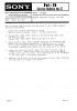
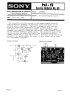
Please find below Sony's service bulletin how to test the VFETs. For this, remove the grill on the bottom of the amp, unscrew the VFET screws and just pull tem. There are not soldered, but slotted (the oxidation inside the brass slots being one of the typical revamp actions). Duly cleaning the thermal paste (isopropanyl or white spirit) would be recommended, as it has electrically isolating properties, potentially disturbing the measurements.

As EW recommended, mark each VFET original location before pulling, or directly afterwards cleaning one.

Now, depending on the outcome of the measurements, you are either very lucky or very unlucky. If the VFETs are faulty, then yo better sell off the amps in parts, forget about finding new VFETs (I need some parts). If they are ok, then please never switch on again the amp until fully refurbished.

Despite being a delicate VFET amp, the circuit topology is such that the VFETs get easily killed by various problems caused by aging, such as:
- poor ground connections of the main amp board (connector oxidation)
- poor VFET lead connection (slot oxidation)
- failure of the infamous (hated) double-diode in the bias circuit, aka suicide diodes
- failing driver transistors,
- failing (aging) caps
- etc.

Can you perhaps tell more exactly how 'it died on you' ? If both channels died at exactly the same time, then it might be a common fault, such as the speaker protection relay. Do you hear the relay click open when you switch on the amp? Also, the headphones are tapped off the output signals before the relay, so they should still work if the relay doesn't open. If they don't, then I'm very afraid that the VFETs have died on you, unless the power supply has failed for some reason (but that would be really rare).

Then, there have been some very good threads at AK on this amp, search around, notably concerning the double diodes and how to replace them.

And test first the VFETs as below.... Please tell what the measurement results are.

good luck,
ozzy

SonyHiFiSB49TA-46505650Page1.jpg


SonyHiFiSB49TA-46505650Page2.jpg
 
Hi Posters.
Thanks for the info, what actually happened was, I was interchanging speakers on this amp, but did not turn off amp while doing so, I know I know, and lost all output to the speakers, I have not tried it with headphones will do that and post the result, what I have noticed is that 3 of the Vfets do not get as hot as the rest, ( 5 very hot, 3 just warm ). can I use the same thermal paste as used on computer chips..
thanks.
Wal
 

Attachments

  • IMG_0608.jpg
    IMG_0608.jpg
    73.3 KB · Views: 87
ai ai ai, that might have fried some VFETs, depending on the protection circuit if it has acted quicker or slower then the VFET respons. These VFET amps are regular class-B amps, meaning that they should NOT get very hot. Hence, that is good and bad news at the same time: the good news being that the very hot VFETs are probably alive (faulty VFETs do normally not conduct, so they would be cold), while the bad news is that the 3 just warm might be faulty (difficult to say if they heat up themselves or if they are being heat up by the heat sink). In other words, you gotta test each one them.

Then, the fact that some of them get very hot means that the idling current is way too high, meaning that this amp needs a serious refurbishment not limited to capacitors only. I would not switch this amp on again to avoid VFET destruction until you have done the refurbishment.
 
can I use the same thermal paste as used on computer chips..
No. Well, I guess it depends on what you're talking about, but most CPU compounds are too thick (and some are electrically conductive).

But you're a long way from needing to worry about that right now.
 
Update

Progress so far

Tested transistors as per Oilmaster instructions results as follows if I did it right.

With DVM set at 800Ohms.

Transistor S to D S to G D to G
1 1.9 738 737
2 2.3 735 734
3 2.3 OL OL
4 1.7 OL OL
5 1.9 OL OL
6 1.8 OL OL
7 1.9 777 776
8 1.9 310 311
OL = NO reading

With Avo 8 set at 1KOhms

Transistor S to D S to G D to G
1 9 nr nr
2 9 28 nr
3 9 nr 29
4 8.5 nr nr
5 8.5 nr nr
6 8.5 nr nr
7 8.5 28 28
8 8.5 27 27
nr = No reading needle stays on zero.

More tomorrow, Wal
 
Last edited:
Progress so far

Tested transistors as per Oilmaster instructions results as follows if I did it right.

With DVM set at 800Ohms.

Transistor S to D S to G D to G
1 1.9 738 737
2 2.3 735 734
3 2.3 OL OL
4 1.7 OL OL
5 1.9 OL OL
6 1.8 OL OL
7 1.9 777 776
8 1.9 310 311
OL = NO reading

With Avo 8 set at 1KOhms

Transistor S to D S to G D to G
1 9 nr nr
2 9 28 nr
3 9 nr 29
4 8.5 nr nr
5 8.5 nr nr
6 8.5 nr nr
7 8.5 28 28
8 8.5 27 27
nr = No reading needle stays on zero.

More tomorrow, Wal

If you click "reply to thread" the formatting comes back in the reply window and your chart is pretty readable.

The source to gate and drain to gate tests must be conducted in both directions "same as a diode". If your meter has a diode check function, now's a good time to use it. The resistance should be infinite (0L) in one direction and somewhere around 1Kohms in the other. There should be ~0.7V drop across the junction in the conducting direction using diode test.

Good luck. I have a bad feeling about this one but I'm often wrong...
 
Last edited:
Don't let me touch that, the last one, and maybe the only one, and an old friend and co-worker who also worked on electronics and does sound and runs a studio.

Leave it to me to line the damn fets up on the bench, few days later, I put the friggen things in WRONG.They got shuffled on the bench and if I would have looked I could have seen they where in wrong, but noooooooooooo.

all the crap I work on and have worked on, I had to pop a damn stereo that has rare parts, and for a friend.


aaaaaaaaaaarg
It wasn't even that broke.
 
If you click "reply to thread" the formatting comes back in the reply window and your chart is pretty readable.

The source to gate and drain to gate tests must be conducted in both directions "same as a diode". If your meter has a diode check function, now's a good time to use it. The resistance should be infinite (0L) in one direction and somewhere around 1Kohms in the other. There should be ~0.7V drop across the junction in the conducting direction using diode test.

Good luck. I have a bad feeling about this one but I'm often wrong...

Indeed, the 'same as diode' reading should be made using a diode tester (standard function of most DVMs), the service bulletin is not so clear on that. The diode test actually provides you the forward voltage drop, which for a regular diode is around 0.65 volts. Some DVMs display 650 (i.e. mVolts), other will display 0.65 (i.e. Volts). The tricky thing is that the polarity of the diode test is important, I mistakenly made bad readings... Anyway, if a VFET is fried, they most often are shorting during a diode test. Again, the thermal paste is another cause for bad readings, make sure it's not causing you wrong readings.

good luck
ozzy
 
Two more Sony Service Bulletins 57 and 66

Please see attached two more Service Bulletins which concern the issues with TA-5650
Service Bulletin 57 - Repeated failure of V-FET
Service Bulletin 66 - New power supply board
Greetings
 

Attachments

  • Sony TA-5650 Service Bulletin 57 VFET falures.png
    Sony TA-5650 Service Bulletin 57 VFET falures.png
    58 KB · Views: 172
  • Sony TA-5650 Service Bulletin 66 new PS.png
    Sony TA-5650 Service Bulletin 66 new PS.png
    92.5 KB · Views: 168
Please see attached two more Service Bulletins which concern the issues with TA-5650
Service Bulletin 57 - Repeated failure of V-FET
Service Bulletin 66 - New power supply board
Greetings

Hi Mckee,
many thanks for posting these service bulletins, Although I knew about some of the modifications via various AK threads, I never saw the original service bulletins. I can only save them as a PNG file; is there a possibility that you email me them in a different format?

cheers,
ozzy
 
Back
Top Bottom