

You are using an out of date browser. It may not display this or other websites correctly.
You should upgrade or use an alternative browser.
You should upgrade or use an alternative browser.
SONY 5650 Vfet amp advise before I start
- Thread starter gummy
- Start date

Oilmaster
Sonycus Peritum
Hmm, strange outcome. If they are 'open loop' then they cannot conduct a high current which causes them to heat up. Personally, I made several times the mistake with the probe's polarity during the diode test as the VFET is mostly laying on his back (on his cap) while the SB image shows the VFET with the legs down, not to mention you can trun the VEFT around. Can you please redo the diode tests and measure the values in both directions? Also, before anything else, can you test if your DVM is working properly by testing a new/working diode, and if the probe cables are plugged in the right DVM terminals?
Ozzy
Ozzy
Oilmaster
Sonycus Peritum


thefragger
Certified Crazy.


Another update
OK I have done the following with a new 1n4005 diode I get the following OL and 0.549v
my DVM is a pro model about 1 year old, re tested the transistors as
follows. 2SJ18 first, neg on S pin, 1 reads OL 2 = OL 7 = OL 8 reads 0.196
with neg on G 1 reads 0.512 2 = 0.510 7 = 0.536 8 = 0.236.
Now the 2SK60 neg on S 3 reads 0.555 4 = 0.529 5 = 0.554 6 = 0.552, with neg on G they all read OL.
I reckon only No 7 is duff, am I correct.
Wal.
OK I have done the following with a new 1n4005 diode I get the following OL and 0.549v
my DVM is a pro model about 1 year old, re tested the transistors as
follows. 2SJ18 first, neg on S pin, 1 reads OL 2 = OL 7 = OL 8 reads 0.196
with neg on G 1 reads 0.512 2 = 0.510 7 = 0.536 8 = 0.236.
Now the 2SK60 neg on S 3 reads 0.555 4 = 0.529 5 = 0.554 6 = 0.552, with neg on G they all read OL.
I reckon only No 7 is duff, am I correct.
Wal.
Oilmaster
Sonycus Peritum
Hi Wal,
Well, those are actually positive results, except for #8 ! I just tested some of my own VFETs, and I now remember something: the service bulletin is a bit misleading... because one is NPN and the other is PNP, so the test instructions should be:
2SJ18:
S to D .... appr. 1~2 ohm (my good VFETs measure 0.8 to 1.5 ohm)
S to G .... same as diode (my good VFETs measure 0.462~0.491 volt)
G to S .... OL (open)
D to G .... same as diode (my good VFETs measure 0.460~0.490 volt)
G to D .... OL (open)
2SK60:
S to D .... appr. 1~2 ohm (my good VFETs measure 1.5 to 2.6 ohm)
and now with reversed polarity:
G to S .... same as diode (my good VFETs measure 0.482~0.507 volt)
S to G .... OL (open)
G to D .... same as diode (my good VFETs measure 0.477~0.497 volt)
D to G .... OL (open)
Now, having a bag of faulty VFETs at hand as well (who doesn't...), the results would be OL between G and S (either way, i.e. really open), and close to 0 mV between D and G (either way, i.e. shorting).
Results can vary amongst rankings, the above results cover a dual set of rank 54 and rank 26.
I fear that #8 is sort of halfway to silicon heaven.
For sake of clarity, can you please do all 3 measurements for each VFET?
cheers,
ozzy
Well, those are actually positive results, except for #8 ! I just tested some of my own VFETs, and I now remember something: the service bulletin is a bit misleading... because one is NPN and the other is PNP, so the test instructions should be:
2SJ18:
S to D .... appr. 1~2 ohm (my good VFETs measure 0.8 to 1.5 ohm)
S to G .... same as diode (my good VFETs measure 0.462~0.491 volt)
G to S .... OL (open)
D to G .... same as diode (my good VFETs measure 0.460~0.490 volt)
G to D .... OL (open)
2SK60:
S to D .... appr. 1~2 ohm (my good VFETs measure 1.5 to 2.6 ohm)
and now with reversed polarity:
G to S .... same as diode (my good VFETs measure 0.482~0.507 volt)
S to G .... OL (open)
G to D .... same as diode (my good VFETs measure 0.477~0.497 volt)
D to G .... OL (open)
Now, having a bag of faulty VFETs at hand as well (who doesn't...), the results would be OL between G and S (either way, i.e. really open), and close to 0 mV between D and G (either way, i.e. shorting).
Results can vary amongst rankings, the above results cover a dual set of rank 54 and rank 26.
I fear that #8 is sort of halfway to silicon heaven.
For sake of clarity, can you please do all 3 measurements for each VFET?
cheers,
ozzy
Last edited:
Oilmaster
Sonycus Peritum
The fact that theirs a SB 66 implies that there's, (at least), 65 others. Is this correct? Does anyone have them all. My 5650 is in need of service also.
Well there are 65 others, but not particular for the VFET series. The 3 SB listed in this trhead are the ones known to me. Perhaps somebody else knows about another one?
Has anybody or any site has them all? That's a question I had many times. AK database would be great to create a subgroup for only Sony SBs.
Oilmaster
Sonycus Peritum
This 5650 rebuild thread is a good starter to get a feeling what you would be up to...

OK Oilmaster...they are 'N-Channel' (2SKxxx) and 'P-Channel' (2SJxxx). 
I got your PM gummy, and I have a hard time sorting through your readings. Don't make this harder than it has to be.
Here's the pinout of a power VFET, sitting 'dead-bug' style, on its back:

Note that the pins are not aligned with the centerline of the device...orient the device so that the 'short distance' between the pins and the mounting hole matches the drawing.
To check the device, you need a digital meter, as many analog meters pass too much voltage and current when in diode test mode. At any rate, with the meter set to measure resistance, simply take a measurement between the source and the drain. Lead orientation doesn't matter here. You should measure between 1 and 2 ohms. If the device passes that test, then it's time to check the gate.
Set your meter for its diode test function (the readout in this mode is in volts). To test the gate, you must first note if you have a N-channel (2SK) or P-channel (2SJ) device. If you have an N-channel device to test, connect the positive meter lead to the Gate, and the negative lead to the Source. Most meters will read about 0.590V (590mV) for a good N-Channel device. Now remove the meter lead from the Source pin and attach it to the Drain (the case of the device). You should read about the same here as you did when measuring from the Gate to the Source.
If you have a P-channel device, the procedure is the same...check drain-to-source resistance, looking for a reading of about 1 to 2 ohms. The difference is that because we now have a P-channel as opposed to an N-channel, our 'diode' is reversed. So when testing the Gate of a P-channel device the negative is attached to the Gate, and the positive goes to the Source and Drain. You will typically measure a little less (0.550mV or so) for a good P-channel device than you do with the N-channel device.
It isn't a bad idea to reverse check the gate junction...connect the negative lead to the Gate of the N-channel device and the positive to the Source and Drain and make sure that the junction does not conduct (and the opposite for a P-channel device...connect the positive lead to the Gate and the negative to the Source and the Drain).
Dead VFET's typically are open in the resistance measurement from Drain to Source. Or the Gate->Source or Gate->Drain 'diode' is shorted (0V measured), or if not shorted, a very low value is measured (200mV or something like that).
Here's a Word doc on FET testing: http://www.audiokarma.org/forums/showpost.php?p=764244&postcount=2
I got your PM gummy, and I have a hard time sorting through your readings. Don't make this harder than it has to be.
Here's the pinout of a power VFET, sitting 'dead-bug' style, on its back:
Note that the pins are not aligned with the centerline of the device...orient the device so that the 'short distance' between the pins and the mounting hole matches the drawing.
To check the device, you need a digital meter, as many analog meters pass too much voltage and current when in diode test mode. At any rate, with the meter set to measure resistance, simply take a measurement between the source and the drain. Lead orientation doesn't matter here. You should measure between 1 and 2 ohms. If the device passes that test, then it's time to check the gate.
Set your meter for its diode test function (the readout in this mode is in volts). To test the gate, you must first note if you have a N-channel (2SK) or P-channel (2SJ) device. If you have an N-channel device to test, connect the positive meter lead to the Gate, and the negative lead to the Source. Most meters will read about 0.590V (590mV) for a good N-Channel device. Now remove the meter lead from the Source pin and attach it to the Drain (the case of the device). You should read about the same here as you did when measuring from the Gate to the Source.
If you have a P-channel device, the procedure is the same...check drain-to-source resistance, looking for a reading of about 1 to 2 ohms. The difference is that because we now have a P-channel as opposed to an N-channel, our 'diode' is reversed. So when testing the Gate of a P-channel device the negative is attached to the Gate, and the positive goes to the Source and Drain. You will typically measure a little less (0.550mV or so) for a good P-channel device than you do with the N-channel device.
It isn't a bad idea to reverse check the gate junction...connect the negative lead to the Gate of the N-channel device and the positive to the Source and Drain and make sure that the junction does not conduct (and the opposite for a P-channel device...connect the positive lead to the Gate and the negative to the Source and the Drain).
Dead VFET's typically are open in the resistance measurement from Drain to Source. Or the Gate->Source or Gate->Drain 'diode' is shorted (0V measured), or if not shorted, a very low value is measured (200mV or something like that).
Here's a Word doc on FET testing: http://www.audiokarma.org/forums/showpost.php?p=764244&postcount=2
Last edited:
Oilmaster
Sonycus Peritum
OK Oilmaster...they are 'N-Channel' (2SKxxx) and 'P-Channel' (2SJxxx).
Oops, indeed.... too quick write-ups.... shame on me.

Artie
Super Member
This 5650 rebuild thread is a good starter to get a feeling what you would be up to...
Excellent. Thanks, great thread.
Another update
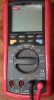
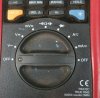
Well I have tried to carry out ecowars instructions (using my DVM see pic) and here are the results.
Tested on 800KOhm range. 2SK60 transistor 1 = 1.9. 2 = 2.1 3 = 2.4 4 = 1.8 5 = 2. 6 = 1.9 7 = 2.0 8 = 0.9
Now the diode test, gate to source transistor 2SJ18 1 = 0.525 2 = 0.524 7 = 0.547 8 = 0.239 on reverse source to drain they are they same or within 0.001 these are the PNP ones.
Now for the others 3 = 0.565 4 = 0.564 5 = 0.564 6 = 0.562 on reverse gate to drain the readings are the same. on the last check on ecowars post they are all OL except No8.
So it seems No 8 is kaput, HELP I need a 2sj18 transistor HE-54 rank, I thought I had located some NOS transistors but on checking they were not Vfets, little diode has some replacements but are unable to supply any tech info on them, If anyone can Help it would be most welcome, if I am unable to get replacements it's a waste of time carrying out any restoration of this amp, as you have probably surmised I am a complete newbie to this hobby but I am trying to do my best, with your help I may triumph.
Thanks all.
Wal
Well I have tried to carry out ecowars instructions (using my DVM see pic) and here are the results.
Tested on 800KOhm range. 2SK60 transistor 1 = 1.9. 2 = 2.1 3 = 2.4 4 = 1.8 5 = 2. 6 = 1.9 7 = 2.0 8 = 0.9
Now the diode test, gate to source transistor 2SJ18 1 = 0.525 2 = 0.524 7 = 0.547 8 = 0.239 on reverse source to drain they are they same or within 0.001 these are the PNP ones.
Now for the others 3 = 0.565 4 = 0.564 5 = 0.564 6 = 0.562 on reverse gate to drain the readings are the same. on the last check on ecowars post they are all OL except No8.
So it seems No 8 is kaput, HELP I need a 2sj18 transistor HE-54 rank, I thought I had located some NOS transistors but on checking they were not Vfets, little diode has some replacements but are unable to supply any tech info on them, If anyone can Help it would be most welcome, if I am unable to get replacements it's a waste of time carrying out any restoration of this amp, as you have probably surmised I am a complete newbie to this hobby but I am trying to do my best, with your help I may triumph.
Thanks all.
Wal
Attachments

 :tears: