Harolda
Well-Known Member
I am working on a TTS8000 which has very similar electronics to the PS8750 speed control. I am also now in the process of designing an alternative solution for the OKI MSM5576 oscillator that delivers the 240Hz, 480Hz and 960Hz signal. This is the same in both the TTS8000 and the PS8750!
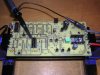
It involves a CD4060BC counter IC, a 3.932160Mhz xtal (same as in the TTS8000 and PS8750), 2 resistors and maybe 2 caps. This will supply the 240Hz, 480Hz and 960Hz square wave signals. I now integrate this solution (after testing a small proto) to a complete new servo board PCB for the TTS8000 due to a lot of issues with bad pad's on the original PCB.
The CD4060BC has the following output that can be used to divide the xtal frequency of 3.932160Mhz:
Pin3: Q12: divider 2^12=4096 --> output frequency is 3932160/4096=960Hz
Pin2: Q13: divider 2^13=8092 --> output frequency is 3932160/8092=480Hz
Pin1: Q14: divider 2^14=16384 --> output frequency is 3932160/16384=240Hz
Voltage input is the same as for the MSM5576. rerouting of the signals is required since the pin connections are different and because the CD4060 is a 16pin IC. 8 connections are used vs the 7 used on the MSM5576
I am thinking that a small PCB that can be installed in a 14pin dip socket can be a solution for both the PS8750 and TTS8000.
So the change would look like
1) desolder OKI MSM5576 IC
2) mount 14pin dip socket
3) mount custom adapter PCB on the 14pin dip socket that contains:
a) the CD4060BC IC
b) the required resistors
c) the rerouting of the signals to the correct MSM5576 positions
4) Maybe an update of the oscillator coupling caps.
I am not yet sure if this can be done with maintaining the old xtal or that a new xtal has to be installed on the adapter PCB. The xtal is coupled to the CD4060 ic using a series and parallel resistor
This is an example for a 1Khz output. In our case we would use output 1,2 & 3:

This is not much different than the MSM5576 except the additional ground connection for pin 12 (reset)
In the PS8750 the speed control board is a seperate PCB, in the TTS8000 everything is integrated on one PCB.
This gives us also the option to design a modern PCB for the PS8750 with little effort that takes care of:
- A failing MSM5576 IC with the solution i described above
- The through board connections with a modern 2-layer PCB design
- All new components since all other IC's are available
What do you think?
It involves a CD4060BC counter IC, a 3.932160Mhz xtal (same as in the TTS8000 and PS8750), 2 resistors and maybe 2 caps. This will supply the 240Hz, 480Hz and 960Hz square wave signals. I now integrate this solution (after testing a small proto) to a complete new servo board PCB for the TTS8000 due to a lot of issues with bad pad's on the original PCB.
The CD4060BC has the following output that can be used to divide the xtal frequency of 3.932160Mhz:
Pin3: Q12: divider 2^12=4096 --> output frequency is 3932160/4096=960Hz
Pin2: Q13: divider 2^13=8092 --> output frequency is 3932160/8092=480Hz
Pin1: Q14: divider 2^14=16384 --> output frequency is 3932160/16384=240Hz
Voltage input is the same as for the MSM5576. rerouting of the signals is required since the pin connections are different and because the CD4060 is a 16pin IC. 8 connections are used vs the 7 used on the MSM5576
I am thinking that a small PCB that can be installed in a 14pin dip socket can be a solution for both the PS8750 and TTS8000.
So the change would look like
1) desolder OKI MSM5576 IC
2) mount 14pin dip socket
3) mount custom adapter PCB on the 14pin dip socket that contains:
a) the CD4060BC IC
b) the required resistors
c) the rerouting of the signals to the correct MSM5576 positions
4) Maybe an update of the oscillator coupling caps.
I am not yet sure if this can be done with maintaining the old xtal or that a new xtal has to be installed on the adapter PCB. The xtal is coupled to the CD4060 ic using a series and parallel resistor
This is an example for a 1Khz output. In our case we would use output 1,2 & 3:
This is not much different than the MSM5576 except the additional ground connection for pin 12 (reset)
In the PS8750 the speed control board is a seperate PCB, in the TTS8000 everything is integrated on one PCB.
This gives us also the option to design a modern PCB for the PS8750 with little effort that takes care of:
- A failing MSM5576 IC with the solution i described above
- The through board connections with a modern 2-layer PCB design
- All new components since all other IC's are available
What do you think?
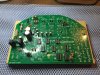
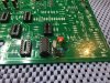


 Nice job Harolda and pat66
 As i have been contact with pat66 with my issues about my sony ps8750 I'm looking forward to also see these new PCB´s and maybe get one when finished.