

You are using an out of date browser. It may not display this or other websites correctly.
You should upgrade or use an alternative browser.
You should upgrade or use an alternative browser.
Sony PS8750 / TTS8000 oscillator replacement proposal with modern CMOS
- Thread starter Harolda
- Start date

pat66
New Member
The new PCB is finished and all works !


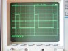

Well an inportant thing to know is that the SN7400, SN7410 and SN7420 must be the 'N' version. I tried LS version with no success. In fact it seems to work but it is not reliable. Some times the platter speeds up, the divider seems to divide by a other value than it should. So Harolda take this in mind for your TTS8000 project.
Well an inportant thing to know is that the SN7400, SN7410 and SN7420 must be the 'N' version. I tried LS version with no success. In fact it seems to work but it is not reliable. Some times the platter speeds up, the divider seems to divide by a other value than it should. So Harolda take this in mind for your TTS8000 project.
Last edited:

Harolda
Well-Known Member
well i also got a little work done to my PCB. Almost everything is populated and checked:

The high voltage section for the strobe is not yet populated. First i want to check all other functions

@pat66. I only have the SN7420A iso SN7420N. I will test this one. Where did you source the 7420?

Now let's check it again and test it on the deck!
The high voltage section for the strobe is not yet populated. First i want to check all other functions
@pat66. I only have the SN7420A iso SN7420N. I will test this one. Where did you source the 7420?
Now let's check it again and test it on the deck!

pat66
New Member
Very nice work Harolda !
I source de 7420 from a french dealer Electronic diffusion.
Your N7420A is perfect. Maybe a 74LS20 should also be used, but what is sure is that the 7400 and 7410 must be the very old normal serie. So the marking on the Ic must be stricly 7400 ou 7410 with no letters between 74 and the other numbers.
My prototype board is working fine but before I order a new batch of PCB, I will add 2 small relays on the board because an other very common failure on the PS8750 and TTS8000 is due to the poor quality of the 2 switchs : 33/45 and Xtal ON/OFF.
So the idea is to use the relay's contacts for switching the signal path and use the original switchs only for energizing the relays. This should solve this problem but this will also need some modifications in the wiring.
I source de 7420 from a french dealer Electronic diffusion.
Your N7420A is perfect. Maybe a 74LS20 should also be used, but what is sure is that the 7400 and 7410 must be the very old normal serie. So the marking on the Ic must be stricly 7400 ou 7410 with no letters between 74 and the other numbers.
My prototype board is working fine but before I order a new batch of PCB, I will add 2 small relays on the board because an other very common failure on the PS8750 and TTS8000 is due to the poor quality of the 2 switchs : 33/45 and Xtal ON/OFF.
So the idea is to use the relay's contacts for switching the signal path and use the original switchs only for energizing the relays. This should solve this problem but this will also need some modifications in the wiring.
Harolda
Well-Known Member
So i connected everything and it did not work correct at the first go. In the process of finding faults I discovered two traces that where not correct, both should have been connected to ground. One was the magnetic head ground trace. After correcting that I got:
1) perfect 45rpm in Xtal mode with <0.1% variation
2) 33.33rpm not yet perfect, too much drift
3) 45 rpm and 33 rpm without Xtal too high speed ( cannot be adjusted with control pots)
4) the electronic braking does not yet seem to work. Motor is switched off when pressing “stop” but no braking occurs (platter spins free and has to be stopped by hand)
The strange thing is that I can use the trimmers on the pcb to set the Xtal speed, I thought these were bypassed in Xtal mode. I will have to look further into this.
I will look further and find any faults, but I also am doubting the speed and Xtal switches and have been thinking about another solution. I like your idea PAT with the relay’s
I the tts8000 I also have an oscillator with a coil that should give a 333khz sine wave. I think this is not present in the PS8750. This circuit now gives me 325khz, and the sine wave is somewhat distorted. I am not sure what the function of this oscillator is, but will also look further into this.
Regards
Harold
1) perfect 45rpm in Xtal mode with <0.1% variation
2) 33.33rpm not yet perfect, too much drift
3) 45 rpm and 33 rpm without Xtal too high speed ( cannot be adjusted with control pots)
4) the electronic braking does not yet seem to work. Motor is switched off when pressing “stop” but no braking occurs (platter spins free and has to be stopped by hand)
The strange thing is that I can use the trimmers on the pcb to set the Xtal speed, I thought these were bypassed in Xtal mode. I will have to look further into this.
I will look further and find any faults, but I also am doubting the speed and Xtal switches and have been thinking about another solution. I like your idea PAT with the relay’s
I the tts8000 I also have an oscillator with a coil that should give a 333khz sine wave. I think this is not present in the PS8750. This circuit now gives me 325khz, and the sine wave is somewhat distorted. I am not sure what the function of this oscillator is, but will also look further into this.
Regards
Harold
Harolda
Well-Known Member
I have solved all issues except the electronic braking. I had a ground connection to an ic where there should be none and I missed a capacitor connection on a transistor. This is what you get when making your own pcb’s with this many parts.
I now have
1) 45rpm perfect with and without xtal lock

2) same with 33 rpm but I sometimes have drops in Xtal mode, I can recognize a signal drop on q13 when I have a speed drop. This is completely stable without Xtal! Switch issue?

Pat I will also look into the relay solution with an additional pcb. For me it makes no sense to order a new pcb with the relay’s integrated, too much cost have already gone into this pcb and all new parts. I will put the switch connector on the relay’s pcb and make a new (flat) cable from the relay pcb to the main pcb.
I hope there is enough power in the power supply to power the relay’s. Do you take the power from the 13v (B+)?
I hope you can share your relay layout.
Regards
I now have
1) 45rpm perfect with and without xtal lock
2) same with 33 rpm but I sometimes have drops in Xtal mode, I can recognize a signal drop on q13 when I have a speed drop. This is completely stable without Xtal! Switch issue?
Pat I will also look into the relay solution with an additional pcb. For me it makes no sense to order a new pcb with the relay’s integrated, too much cost have already gone into this pcb and all new parts. I will put the switch connector on the relay’s pcb and make a new (flat) cable from the relay pcb to the main pcb.
I hope there is enough power in the power supply to power the relay’s. Do you take the power from the 13v (B+)?
I hope you can share your relay layout.
Regards
Harolda
Well-Known Member
I know have a proto with relay's for the xtal and speed switch running with 2 omron G5V-2 relays i had laying around, works perfect!
I am running a speed stability test on the 33rpm now for one hour and will show you the results
After that i will do the same for the 45rpm 1 hour test. Both will be with Xtal on. Speed deviation should be 0.003% with stall on, let's see if we can achieve that.
After that i will run xtal of with manual speed setting.
@pat66, i had a look at the signal of Q20, it is exactly the same as Q2. There are some phase differences between both signals but i think that is ok since both heads are in another position. Brake is still not working as it should. Any other thoughts?
regards
Harold
I am running a speed stability test on the 33rpm now for one hour and will show you the results
After that i will do the same for the 45rpm 1 hour test. Both will be with Xtal on. Speed deviation should be 0.003% with stall on, let's see if we can achieve that.
After that i will run xtal of with manual speed setting.
@pat66, i had a look at the signal of Q20, it is exactly the same as Q2. There are some phase differences between both signals but i think that is ok since both heads are in another position. Brake is still not working as it should. Any other thoughts?
regards
Harold


Harolda
Well-Known Member
Finally the high voltage section for the strobe is also finished and tested. Works like a charm.
The final step is assembly of the complete motor and making a permanent solutions for the speed and stall relay solution.
After that i will start on a plinth.
I intend to use a PUA1500S with the motor but i am thinking of going to a PUA1600L or PUA 7. Any experience with these arms?
The final step is assembly of the complete motor and making a permanent solutions for the speed and stall relay solution.
After that i will start on a plinth.
I intend to use a PUA1500S with the motor but i am thinking of going to a PUA1600L or PUA 7. Any experience with these arms?
Harolda
Well-Known Member
I am still working one the motor, mainly to design a permanent solution for the relays
For your information:
1) I found out that the two speed trim pots on the pcb influence the functioning of the Xtal. It seems that they set a certain reference voltage for the Xtal feedback system. If this is set too high or too low you will still have speed drops. I think this is also true for the PS8750! So if you still have speed drops on your restored deck, then look at the setting of these trim pots.
2) the tts8000 service manual contains a page with waveforms for measurements. The PS8750 sm does not contain this. You can however use many of the tts8000 waveforms for checking your PS8750.
3) the other interesting thing is that the tts8000 has 2 speed detecting heads, where the PS8750 only has one. The second head is placed next to the first and connected to the braking circuit. Was this done to have a faster response to speed deviations?
For your information:
1) I found out that the two speed trim pots on the pcb influence the functioning of the Xtal. It seems that they set a certain reference voltage for the Xtal feedback system. If this is set too high or too low you will still have speed drops. I think this is also true for the PS8750! So if you still have speed drops on your restored deck, then look at the setting of these trim pots.
2) the tts8000 service manual contains a page with waveforms for measurements. The PS8750 sm does not contain this. You can however use many of the tts8000 waveforms for checking your PS8750.
3) the other interesting thing is that the tts8000 has 2 speed detecting heads, where the PS8750 only has one. The second head is placed next to the first and connected to the braking circuit. Was this done to have a faster response to speed deviations?

Finally the high voltage section for the strobe is also finished and tested. Works like a charm.
The final step is assembly of the complete motor and making a permanent solutions for the speed and stall relay solution.
After that i will start on a plinth.
I intend to use a PUA1500S with the motor but i am thinking of going to a PUA1600L or PUA 7. Any experience with these arms?
According to TVK all three Sony tonearms are top notch. I'm looking to get a 1600 at some point in time for my TTS-4000. I love the PUA-7 but it's not an aesthetic match.
What speed deviation are you getting percentage wise now? Awesome work!
Is this a ground up redesign board or are you reengineering the Sony circuit with more readily available ICs?
Cheers
Nathan
Harolda
Well-Known Member
I have speed deviations <0.05%. I will post some measurements
I only reengineered on item, which is the circuit that provides the 240h, 480hz and 960hz for the Xtal system. I had to do this since the original msm5576 ic is not available anymore. The rest is carry over with some improvements in the high voltage section for the strobe lamp.
I had to learn a lot by doing and trying to understand the circuit. For example you cannot use electrolytics in positions where Sony used tantalums. I did not get the correct waveforms in some positions and found out that the electrolytics caused the problem. With the original tantalums everything was fine. These where a sample hold circuit and a low pass filter circuit.
I only reengineered on item, which is the circuit that provides the 240h, 480hz and 960hz for the Xtal system. I had to do this since the original msm5576 ic is not available anymore. The rest is carry over with some improvements in the high voltage section for the strobe lamp.
I had to learn a lot by doing and trying to understand the circuit. For example you cannot use electrolytics in positions where Sony used tantalums. I did not get the correct waveforms in some positions and found out that the electrolytics caused the problem. With the original tantalums everything was fine. These where a sample hold circuit and a low pass filter circuit.
Harolda
Well-Known Member
So finally the tts8000 motor is finished. Today i put the bottom plate on and checked everything for the last time.
Next up is a tts4000 or a psx-800. But first i think i finish the phono amps on my AU-X1
I have one PCB left for a TTS8000, so if you are interested PM me.
regards
Next up is a tts4000 or a psx-800. But first i think i finish the phono amps on my AU-X1
I have one PCB left for a TTS8000, so if you are interested PM me.
regards
What does your tts-4000 need? 
Harolda
Well-Known Member


Some progress on the plinth at last. The plinth is build out of multiple layers of 18mm birch plywood. Each layer is cnc machined. I will only use a Sony pua 1600L tonearm on this one.
I made edges out of rosewood inlays to be able to route the edges after veneering with rosewood veneer. The trial fit works for the tts8000. The tone arm is being assembled and will be trial fitted soon