• The move to the new server is done. There are some software and database maintenance updates in process. This has us passing the hat around to help out. We appreciate any donations. Seriously, even a dollar helps. The payment page may be found here - https://www.audiokarma.org/support.html

Sony STR-7065--PCB char-is it a make or break issue?

Kevin Kreigh

New Member
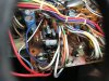
image.jpg image.jpg All,
New here and newbie to repair. Stick with description please!
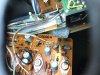
I picked up an 7065. Did some cleaning and inspection. Several caps seem new? Speaker B and C channels right, sometimes left were not working. Speaker A seemed to be OK. I noticed up near speaker inputs on supply board there was a component that did not have completed solder joint—one leg freely moving. Side note-kind of suck at schematics and this one is not complete-so unsure on specific part- PCB area has some charring, so can’t make out part number on board-but it’s labeled 5w22003. I’ll attach picture. Reflowed solder joint and had all channels active, but with some distortion on B/C channels which now seemed to be isolated to left channel. Speaker A channel still OK. Now, during testing, I made big mistake of not securing board and ended up shorting/frying R704, R705 and R827 I guess bc I bumped the mounting post (another story-but I’ll post picture). I will replace those resistors.
The real big question is the PCB char a make or break issue? Craigslist deal owner didn’t have much to add regarding history.
If you made it through this post and have any direction/hints/tips—thank you!
 
Register to hide this ad
Your receiver has a tuner, but this is not a tuner issue. Moving from tuner forum to solid state.
 
Welcome to AK!

Don't worry about the heat discoloration on the board. Every 7055 / 7065 on the planet is discolored in that area.

The component you're asking about is R802, a 5W 220 ohm wirewound resistor. If you replace it, you can leave the leads long and stand it off from the board a little farther. The same can be done for the other large resistors in that area, and when you put it all back together, bundle the wires away from that area as much as possible to allow more air flow.
 
I picked up a fix and repair one a few months ago. Power supply and parts of the amp circuit had some rough repairs and power supply area like in your first picture mine was probably worse. Those 4 little mylar caps I gather were once green in mine were black too and one had split up the middle. Compared to mine looks like a big resistor is missing between the 220 ohm 5W resistor and the trimmer. Yours fits what is actually on the board layout in the service manual. Mine had a number of resistors near the driver transistors that were brown in the middle it looks like with yours there may have been two or three at the bottom corner of the board that got vaporized. That Sony 2SC1124 transistor may have gotten blown too - black on the board underneath it from the picture.

I believe Sony made changes to some big resistors in the power supply - there may be two sets of values they used. Mine has R840 in there to the left of the trimmer in the first image, but another layout of the board does not have it so looks like yours. That 220 ohm resistor runs so hot over time it may be the one that fries those four little mylar caps. I agree that corner of the board up near the rectifier diodes and those mylar caps on most of these guys has gotten pretty dark over the years.

Looking at the layout I see 1.5k for R705, 22k for R704, and 47 for R827, all should the 1/4 W 5% carbon. R704 is between the emitter of Q705 (2SC1124) and the base of Q701 (2SA678). I see R827 was between the -63 V supply and the emitter of Q705 and from there R705 to the B of Q705. Could be more collateral damage. Gather something got against the bracket and shorted part of the circuit down in that corner to ground. Probably that section of trace that is supposed to be around -50V got shorted to ground.
 
<disclosure>I didn't look at the schematic</disclosure>

but I have some use a metal dale or similar to mount to a chassis and run pig tails to the board to offload some of the heat in the area. i don't recall my little Sony receiver (7015?) having this issue.

something like: https://www.mouser.com/ProductDetai...GAEpiMZZMtlubZbdhIBIEidPY%2Bx/LaaKkLJ1C3bEXw=

I'd clean up the board with some IPA and get it running. If you need to order parts and are comfortable with soldering in replacements, a bigger wattage resistor might be a good thing.
 
Back
Top Bottom