• The move to the new server is done. There are some software and database maintenance updates in process. This has us passing the hat around to help out. We appreciate any donations. Seriously, even a dollar helps. The payment page may be found here - https://www.audiokarma.org/support.html

Sony STR-VX5 power supply trouble in paradise

redcarguy

New Member
I was given a dead Sony STR-VX5 receiver, which I take to be a reasonable unit; thought I would fix it up and send it down the road to some deserving soul ...

I'm not familiar with this unit at all, it has the "Legato linear circuit" and "pulse power supply" ... and, of course, I have no schematics and an online search hasn't shown any readily available.

It doesn't look imposing, but inside it's built like a tank, every little thing is marked on the boards, every post is perfectly wire-wrapped, and everything is .just.so. inside.

Powered up, no display, nothing. Everything looks in good shape, there's SOME juice going around inside and all that, and no cold solder joints.

I figured out it's not getting enough juice, but the topology is a little odd ...

120 volts AC goes to the main board, dances around a bit and comes out at two points labeled "power unit" at 165 volts DC. Rock solid, 165vDC, while the 120vAC wavers a bit from 116 to 118.

Even though it's a little weird, I figure that's probably not the problem.

That 165vDC leaves the main board via a pair of 14 gauge wires and disappears into a separate aluminum-encased "power supply" ... coming OUT of that power supply, very clearly labeled on the wire-wrapped circuit boards, are ground wires and what are supposed to be three things : 45vDC, 45vDC, and 9vDC.

But here's what's showing vs. labeled ...

labeled +45vDC actual is +22vDC
labeled +45vDC actual is +18vDC
labeled +9vDC actual is +9vDC

So I opened the "power supply" box (which took about a half hour, no joke, it slips together tight, then it's screwed together, then some of the parts inside use the case as a heat sink, so they have to be separated to get it all open.

Inside is a fairly complicated power supply gizmo, the heart of which is a smallish transformer, with, I kid you not, something like 18 taps. I haven't looked at it in detail, but there's a lot going on, transistors, resistors, caps everywhere, and a complex topology. I could identify the 9v tap labeled on the circuit board, but the others are really murky.

Also, the two supposed-to-be +45vDC circuits are quite different from each other in how they run around the boards inside the power supply after exiting the transformer.

Thoughts? This seems one one level to be just a transformer issue, but I may be wrong. It looks fine, and hasn't overheated or broken down that I can tell. Also, I have zero experience with these "pulse power supply" things, or switch mode power supplies, if that's even what this is.

Replacing the transformer would be a very difficult task; it, like many other components, is built into a structure that's built into another and another. With very little space to work. So I don't want to do that unless I can verify that's the issue.

Thoughts? Ideas? Opinions? Experience? Thank you!
 
Register to hide this ad
Greetings and welcome to the asylum. probably ps needs a rebuild and actually isn't a great investment when other stuff including sony is out there. but for learning or whatever okay.. just no service manual so probably not high on the sony list.
 
Wondering if I could just feed it 45 volts from another linear power supply and see what happens? Not like I could break it more than it's already broken.

Jeff Rowland would do that when his amps switching power supplies failed, if you sent it back they would rebuild it as a dead simple linear and it's good to go.
Of course, that's after giving this major song and dance about how superior his switching power supplies were.

How much 45 volt juice should I be prepared to give it? It's a receiver / amp rated at 55 wpc, I'm not going by the sticker on the back because I assume a lot of the demand at the power cord is driven by the power supply, and if I'm eliminating the power supply .... well, you know.
 
I used to work on SMPS. One of the biggest problems with the ones I worked on was cap failure. I'm not sure special caps existed for SMPS back then but the general purpose caps had the end caps bulging out if they did not take into account the rather high voltage spikes found in a SMPS.

If you're going to change anything out change the caps out first with a good SMPS cap like the Nichicon PJ or PS series depending on size.

Nichicon PJ
http://nichicon-us.com/english/products/pdf/e-pj.pdf

Nichicon PS
http://nichicon-us.com/english/products/pdfs/e-ps.pdf

The transformer is probably fine as long as it is not burnt up looking. They are easy to check with a DMM.

Sometimes you can shock them into starting, oscillating, with freeze spray and that can lead you to bad cap or part but it does not always work.


Can you post any pics?
 
I'll check the caps again, but they all looked fine. In fact, everything looks fine, and all the components I can test on-board are testing OK.

I think I'll agree with you it's not the transformer, since I'm getting the full 9v where it should, and then fractional voltages everywhere else; I'd think if the transformer was junk, I'd be getting zero from one or more of the taps down the line.

I just found a thread by a former Sony tech who said Sony didn't expect techs to diagnose or repair those switch mode power supplies because they were too difficult and time-consuming to diagnose when something went wrong. And that's WITH the factory manual I don't have!

I'd post pictures, but frankly it just looks like a bunch of circuit boards with some very neat layouts and wire wrap.
 
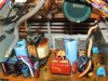
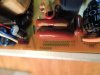
Okay, here's pics of the PS with the outer casing/heat sink removed ... I love the way they label EVERYTHING, including DANGER, and little dividing lines between various sections
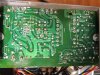
And then the back side of the board ...

The big orange and black wires are where the 165vDC come in ...

The little white wire is supposed to be +9, and it is.
The blue is supposed to be +45, and it's +22
The red is supposed to be +45 and it's +18

I don't see any cap names other than Nichicon anywhere in the unit

DSCN1847.JPG DSCN1849.JPG DSCN1850.JPG
 
Well I see one cap that I would replace for sure. That little Nichicon 100uF, 16V. It's not that Nichicons are bad or anything but I bet there are some serious spikes beyond 16V on that cap if you look at it with an O-scope. These little 16V caps used to fail all the time in the SMPS I used to work on.

If this were me machine gunning it, as they say, I would replace all those electrolytic caps. I would use the same exact uF rating, so you don't disturb the resonance of the circuits, but go up as high as possible on the voltage rating as can size and lead spacing permit.

Those SE and baby blue Nichicons tell me these caps have been around for several decades and have lived a hard life. I really doubt they were made to stand up to the rigors of SMPS life.
 
Well, that's a reasonable approach. You're right, I hadn't noticed the 16v, that's a good point about spikes.
Will do; it shouldn't take more than a couple weeks to find the caps and get them in there (bet is, I don't find them in my parts bin or anywhere within 50 miles, so it's online).
Everything is really tight in there, not sure I could shoehorn much, although I can go up a good distance and cocked sideways this way and that.
Yours is a good reminder that caps are always a good place to start, and I've heard that several times about SMPS ... the voltages threw me
Speaking of caps, I'm busy re-capping the crossovers in my otherwise-mint $10 AR-2a speakers ... made a huge huge difference
So look for me in a couple weeks, thanks again.
 
You really should use caps made for switching power supplies. If you use any regular cap you may end up recapping it again in a few short years.

Mouser and Digikey should carry the PJ and PS lines I suggested and a few others as well. :beerchug:
 
I really like Nichicon PW for power supply work. Digikey has a great selection of these and gets them to your front door in about 24 hours.
 
Thanks very much ... I'm indebted to your spreading the knowledge ... I don't remember working on a SMPS before this, so wasn't aware the extra demands that design puts on components. I was aware SMPS have a rep for high failure rates and that each one is different, so they are difficult to diagnose ... maybe the failure rate is due to building to a price point and not allowing enough headroom, such as higher voltage caps and so on...
Real estate is at a premium on that board, especially for the little caps, so I may end up with a Frankenstein, with long legs, crooked caps, standoffs, and so on. But it's all hidden inside the solid aluminum power supply box, so no one will know !

Side question ... many of you have more experience, and I've never seen this discussed .... what iron temp do YOU use for swapping board components??
 
All these caps have the dimensions listed in the data sheet. All you have to do is find the diameter of the caps you're replacing and there is a table at the top that tells you the lead spacing for that diameter.

Then just look at the xxuF in the chart and choose the higher voltages with the proper L/S and diameter. Caps have gotten smaller these days so you should be able to find a higher voltage cap very easily. :thumbsup:


I use a Weller soldering station with a temp controlled 42 Watts.
 
Ordered from Digikey, along with some other things I've needed for a while, I think they had it packed and confirmation back in less than an hour.

I like the way you can whittle down what you're looking for by mfg, then voltage, mF, MTBF @ temp, and so on, until you're left with one choice.

To go to higher voltage caps, I had to get into a little larger diameter than I'm comfortable with in that space, but I'll squeeze those guys in there somehow.
The only two caps with serious space restrictions are the tiny 16v ones, so I space-wise went as high voltage as I could.
Ordered a couple extra of each; in case the legs don't like being bent;

What's the temp at the tip? I've been running around 650F but I see others strongly suggest going to 750F for desoldering work
 
I think it depends on what kind of iron you have. The one I have automatically puts more juice on the tip when it senses a temp drop so it stays at a very constant temp.

Perhaps some irons that don't have temp control need more watts when they are used on a big copper strip that acts as a heat sink and lowers the temp of the tip.

The only experience I have with cheap irons was the plug directly into the wall Radio Shack pencil iron I had as a kid. That thing was a POS.

I've only used professional/industrial grade Wellers since then, mostly the temp controlled type.

I really don't have any experience with the other brands, good or bad, so I can't really say what it takes to get the other brands to do a good job. I'm sure somebody that has experience with Brand XX will chime in. :)


P.S. I can give you one tip. Too much temp and too much time = FUBAR PCB traces. :eek:

It would be a good idea to take some POS piece of electronics you have no use for and practice soldering on it before you start working on your valuable stuff. :thumbsup:
 
Last edited:
You can see the caps bulged even in these pics. electrolytic caps new are slightly concave on the tops. Little tight in there but doable.. drop ins should be avail as noted above. I run kester 60-40 31mm at about 680F. You really need a solder sucker though copper braid is okay, just don't keep heat on the same joint very long at all. if you have a rat shack still open they may have their plunger vac pump. worth it. self cleaning and well made and pick up a brass tip dip or digikey has them too and much cheaper if you can wait. If you don't have a temp controlled unit you should get one if you intent to repair more stuff. world of difference. btw.. you dip your tip every time you finish a joint. sponge dips are worthless.

http://www.digikey.com/product-deta...pc&WT.srch=1&gclid=CJ_0zoXQ59ACFdcegQodP_wFwA
 
I've been using both braid and suckers, depending on the situation. My best sucker is really old, maybe 1940's, with a small hardened steel tube, really powerful spring load, the thing will jump out of your hand when you trigger it. There's a replaceable rubber diaphragm inside, although I had to make one last time it needed it. You can hear the air whistle through the thing, ah, they don't make 'em like that anymore.

I've been running 680F, too, but on diyaudio there was a discussion about 750 being better because it gets the solder soft faster and thereby stresses nearby components less. That sorta makes sense, but only if your component lets go right away, otherwise I think you're putting too much heat into it while you alligator wrestle a tiny little gizmo loose.

I have three irons, but one is too small to do anything much, and one is gigantic, I think for repairing bridge girders or UFOs; the cradle for it is about five pounds. So I use the middle iron, an old reliable pro Weller that has a thermocouple tip and can be dialed from around 300 to 800. I usually have it programmed for 680. The tether is about six feet, so I can leave the base on the bench and solder on the floor or inside a speaker cabinet, whatever. I also have a fourth "iron", a Cold Heat, which people deride but it DOES work if you are very fastidious about cleaning the tip and getting it aligned just right with just the right solder and just the right in-line splice ... I use it inside the Ye Olde cars, when there's just a wire or two to touch up; a hot iron anywhere near a couple of these tinderbox cars would be a bad idea.
 
Oh, right. About the Sony. No dice. I swapped all the caps, and .... same thing. This time I got 18v where I shoulda had 45 (same result), but now 31v on the other supposed-to-be-45. So replacing the caps DID work, a bit. But not enough. The trouble runs deep with this unit.

So it's now the Sony Of Many Pieces, and yielded a decent AM antenna, some RCA females, a power cord, a big pile of brass machine screws, and knobs Honestly, that's about it. While put together quite well, it didn't yield much that was interesting enough to bother salvaging.

What IS interesting, though, is what this unit had hidden on its circuit boards ... needing only a couple components :: Shortwave, AM Stereo, phono pre outs, pre outs, a power bump to 100wpc,
 
Hi Folks; I have an STR-VX5 on the bench, humming at about 200 or 300 Hz (guessing). I was about to give up as I'm not a fan of switching power supplies when I discovered the hum level change with some 'chop stick' probing. I tightened the screws holding the primary power supply / amplifier pcb and the receiver is perfectly quiet now! Just thought I would add my 2 cents!
 
Back
Top Bottom