• The move to the new server is done. There are some software and database maintenance updates in process. This has us passing the hat around to help out. We appreciate any donations. Seriously, even a dollar helps. The payment page may be found here - https://www.audiokarma.org/support.html

Sony TA-4650 VFET Amp Restoration

AlexHempel

AK Subscriber
Subscriber
Greetings all,

I purchased a Sony TA-4650 VFET amplifier as a quarantine project and thought I'd start a thread to document my efforts. My Stax headphones go well with warmer, less-fatiguing amps and I left my Pioneer M-22 back in NYC, so this seemed like a good pick-up. Plus, I want to see if the VFET magic is real. Tomorrow I'll be opening it up and putting together a parts list -- I'll post a link to a Google Sheets BOM with all the new caps, trimmers, diodes, etc. once I'm done. Hopefully that will prove useful to someone else in the future.

I jumped on this particular TA-4650 because it appeared to be in very good condition and was described as working. To my surprise, the seller wasn't lying -- I turned it on for about ten seconds and it seems to be fully functional. I'm fairly impressed, especially considering the unit appears to have all-original parts and these Sony VFET integrateds are known for nuking their outputs.

Anyways, here's a picture. Aside from some grime on the pots, a few nicks on the top of the faceplate, and minor corrosion on the top panel, it's in perfect cosmetic condition.
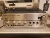
20200322_225046.jpg
 
Register to hide this ad
@PE9ZZ Yes, that's definitely first on my list -- I'm pretty sure the diodes are original, so they'll need to be changed. I was almost hoping the VFETs would be shot so I could try your MOSFET mod.

@rottalpha The Stax are electrostatic, so I drive them with a modded transformer box (SRD-7) connected to the speaker terminals rather than using the phones jack.
 
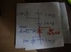
So in addition to the suicide diode replacement, some users on diyAudio recommend a PSU diode mod designed to ensure the 75v + and - supplies are balanced. It involves placing D403 in series and tying the connection between the two diodes to ground. Here's a picture of the updated schematic:

PSUdiodemodta4650.jpg

Posters recommend drilling a hole in the PCB to achieve this, but I don't have access to a power drill at the moment (left some of my supplies in storage thanks to corona). Would it be acceptable to run a jumper around to the ground trace instead? And does anyone know anything about the efficacy of this mod? Thanks!
 
I just tacked on the extra diode on the copper side. This mod is a must-have too. Never understood why the engineers at Sony decided on a floating power supply. Almost criminal...
 
@PE9ZZ Thoughts on replacing the low-power amp board transistors? Is this a recommended operation or unnecessary? My 4650 works but all the amp board transistors have black legs and generally look kind of rough.
 
@PE9ZZ Thoughts on replacing the low-power amp board transistors? Is this a recommended operation or unnecessary? My 4650 works but all the amp board transistors have black legs and generally look kind of rough.
AFAIK these transistors are not prone to failure. I would leave them but then I'm biased against replacing components willy nilly...
 
Rebuilt a 4650 this summer. I've had several issues with the 2SC1124's on the power supply board, replace with KSC2690.

I kinda wanted to replace the small signal transistors for reasons you state, but left them in the end.
 
@ivandezande thanks for that info! Curious what you ended up doing for the filter caps? I found 13 mm spacing KEMETs that I think will screw in properly, but they're the wrong diameter -- gonna need to use a filler of some sort.
 
@ivandezande thanks for that info! Curious what you ended up doing for the filter caps? I found 13 mm spacing KEMETs that I think will screw in properly, but they're the wrong diameter -- gonna need to use a filler of some sort.
I left them haha. The owner didn't want to bother with it, and I couldn't really think of a good solution.
 
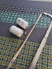
Always read the datasheet! Replacement filter caps should be PEH200MA4470MU2; MB2 has mounting studs. Also, they appear to be slightly too tall. Will update once I've attempted mounting the power supply board.

20200402_122201.jpg
 
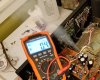
Quick update: wrecked a capacitor today! Did the PSU diode mod, but reversed the polarity because I'm an idiot and not used to working on the backside of PCBs. Well, the end result was one very hot C403 which proceeded to vent gasses all over my room. At first everything was fine and I was happily performing the adjustment procedure, but as soon as I heard the humming I knew I was screwed. Here's a picture, cus why the hell not.

Luckily, the amp board was removed for this test. Just hope my preamp JFETs didn't get totally fried. None of the other caps vented, so am I safe leaving them in? My current plan is to replace C403's counterpart across the board.

Screenshot_20200416-224749_Video Player.jpg
 
Wow! Amazing picture! You're lucky it didn't explode and spewed gunge all over the place...

Yeah, you can prolly leave the others in if they're the right way around.
 
Ok, finally got around to fixing the psu diodes and replacing the blown cap. I also stumbled on a thread where someone mentions changing R313, 314, 363, and 364 to 3.3kohm. Anyone know what this is supposed to accomplish and how important it is?
 
Which thread is that?

Edit: it is this post. Only snag is that the SB mentioned (#62) doesn't say anything about these resistors. I guess that these new values makes the overload protection kick in earlier.
 
Back
Top Bottom