

You are using an out of date browser. It may not display this or other websites correctly.
You should upgrade or use an alternative browser.
You should upgrade or use an alternative browser.
Sony TA-5650 v-fet matching and 1N4148 diodes
- Thread starter Jeff W.
- Start date


Have to match and replace the diff-pair transistors at the front of the amp if you want it better.3. (2-3) On the DC balance check I'm a bit out of spec. on the right channel. It measures 56-57mv. The left channel is at 4mv.
There's no reason why changing the bias would change the offset. Moreover, VFET's (and MOSFET's) require more idle current to eliminate crossover distortion. Specs call for 90mV, and that's where I'd put it (if you're measuring like the manual says).4. (2-4) I went ahead and adjusted the DC bias to a 50mv reading for both channels. This did not change the DC balance readings above. Any advice?
I measure right at the drains of the output devices. Do NOT try this unless you have minigrabber leads for your meter. Get familiar with the foil layout for the amp driver board via the manual. I measure one channel at the drains of Q365 and Q367, and the other channel at the drains of Q315 and Q316. The normal procedure has you measuring only across one of the drain resistors. My method is more accurate, but your goal is now 180mV, since you're measuring across both drain resistors. But like I said, you need good minigrabber leads, which should be attached before power is applied. That, and it may take a good hour for the bias to stabilize, so you don't want to be in a hurry.I know Echowars mentioned taking readings from locations other than those shown in the service manual, so in the meantime I will seek out this thread. I'm so close here and I'd really like to "dial it in" to specifications. Any assistance would be greatly appreciated and I'll "dig" in the meantime.

Ryuuoh: Thanks, yea, it is sweet! I haven't tried it with "real" speakers yet, but I plan to (NS-1000's) over the holiday weekend. I'll hook them up tomorrow and give a report after a few days listening time. Thanks for the encouragement early in the project. I'm glad the caps were a useful find for you as well.
Echowars: by the differential pairs I'm assuming that this is the same recommendation you made to seventies61 "To get offset down, replace Q302 and Q303 (or the other numbers for the opposite channel) with matched pairs. The best replacement would be a Zetex ZTX795A, but you'll need to have them closely matched for gain, which means buying 15 or 20 of 'em." in this thread: http://www.audiokarma.org/forums/showthread.php?t=132374&highlight=5650. I would like to try this if you wouldn't mind telling me how (or steering me to the information) to measure measure the gain so I can match them.
He mentioned (seventies61) in that thread the later Sony manuals showed that DC bias should be set to 50mv for the TA-5650. I thought I had seen that elsewhere as well. My manual does say 90mv so I will correct that. Do you know why the later manuals went to 50mv or if this is true? IIRC there was an issue with them running too hot?
Thank you for detailing your method of measuring the bias and the cautions. My DMM only has probes, but I have some jumpers with alligator clips on each end and will study the procedure as outlined.
Echowars: by the differential pairs I'm assuming that this is the same recommendation you made to seventies61 "To get offset down, replace Q302 and Q303 (or the other numbers for the opposite channel) with matched pairs. The best replacement would be a Zetex ZTX795A, but you'll need to have them closely matched for gain, which means buying 15 or 20 of 'em." in this thread: http://www.audiokarma.org/forums/showthread.php?t=132374&highlight=5650. I would like to try this if you wouldn't mind telling me how (or steering me to the information) to measure measure the gain so I can match them.
He mentioned (seventies61) in that thread the later Sony manuals showed that DC bias should be set to 50mv for the TA-5650. I thought I had seen that elsewhere as well. My manual does say 90mv so I will correct that. Do you know why the later manuals went to 50mv or if this is true? IIRC there was an issue with them running too hot?
Thank you for detailing your method of measuring the bias and the cautions. My DMM only has probes, but I have some jumpers with alligator clips on each end and will study the procedure as outlined.
If you measure bias where the manual says to measure bias, it gets set to 90mV (or 50mV, depending on what you decide). If you measure from the drain of one of the 2SK's to one of the 2SJ's (on the same channel, of course), that voltage will be doubled, so you'd shoot for 180mV (or 100mV). Don't confuse the two measurement methods.
I've never read where the bias should be reduced. Maybe it was, maybe it's BS. That's the problem with working on 30 year-old gear with long out-of-print service manuals and a company that no longer supports this gear.
Many meters have an hfe (transistor gain) function built into them. Works fine for matching small signal devices. If you decide to tackle this, do not assume that the pin layout of your new device is the same as the old. The Zetex transistors, for instance, have the base as the center lead. Most Japanese transistors have the collector as the center lead.
I've never read where the bias should be reduced. Maybe it was, maybe it's BS. That's the problem with working on 30 year-old gear with long out-of-print service manuals and a company that no longer supports this gear.
Many meters have an hfe (transistor gain) function built into them. Works fine for matching small signal devices. If you decide to tackle this, do not assume that the pin layout of your new device is the same as the old. The Zetex transistors, for instance, have the base as the center lead. Most Japanese transistors have the collector as the center lead.

Exactly the same combo I ran my TA-5650 with several years ago and believe it was the best sound I achieved with my NS-1000 speakers (after the TA-N86B). I always listened in the near-field (~5-6') with my NS-1000 speakers, so take care not to over-drive the TA-5650 trying to achieve a 'large' sound with that big sealed box in a far-field (normal) set-up.I haven't tried it with "real" speakers yet, but I plan to (NS-1000's) over the holiday weekend.
For what its worth, my manual also states 90mV.He mentioned (seventies61) in that thread the later Sony manuals showed that DC bias should be set to 50mv for the TA-5650. I thought I had seen that elsewhere as well. My manual does say 90mv so I will correct that. Do you know why the later manuals went to 50mv or if this is true? IIRC there was an issue with them running too hot?
Sony TA-5650 Capacitor List
As promised, but not as neat as I hoped. Some values are used on more than one board so total them carefully when placing an order. *edit* I should add, this is a listing of all the ELECTROLYTIC capacitors. My listening review soon to follow...
Power Amplifier Board
µf-Volts-Quan.
470-6.3-1
100-50-2
100-35-2
47-50-2
47-10-4
10-100-2
10-50-2
Equilizer Amplifier Board
µf-Volts-Quan.
470-35-2
10-100-4
3.3-100-1
Power Supply Board
µf-Volts-Quan.
330-10-1
220-6.3-1
100-100-2
100-50-3
47-50-4
10-50-1
10-25-1
Filter Board
µf-Volts-Quan.
1000-10-2
3.3-100-4
.47-50-2
Main Filter Caps
µf-Volts-Quan.
10,000-50-2
As promised, but not as neat as I hoped. Some values are used on more than one board so total them carefully when placing an order. *edit* I should add, this is a listing of all the ELECTROLYTIC capacitors. My listening review soon to follow...
Power Amplifier Board
µf-Volts-Quan.
470-6.3-1
100-50-2
100-35-2
47-50-2
47-10-4
10-100-2
10-50-2
Equilizer Amplifier Board
µf-Volts-Quan.
470-35-2
10-100-4
3.3-100-1
Power Supply Board
µf-Volts-Quan.
330-10-1
220-6.3-1
100-100-2
100-50-3
47-50-4
10-50-1
10-25-1
Filter Board
µf-Volts-Quan.
1000-10-2
3.3-100-4
.47-50-2
Main Filter Caps
µf-Volts-Quan.
10,000-50-2
Last edited:
Wow! This is a wonderful integrated amp
Having listened for several days now, I am very pleased with the perfomance of the TA-5650. I've had a pair of Yamaha NS-1000 speakers for a while and have to agree with "MX117.MC7150", this is the best these speakers have performed powered by the TA-5650. I've powed them with older McIntosh equipment (MX-110 & MC2105, MX-117 & MC2125), Sherwood SEL-400, and a Sherwood S-9910. None of these combinations were bad at all and some of these other pieces were not fully refurbished. Recently I added a Sony XA5400ES SACD/CD player to the mix so it's not a completely fair comparison. I've also been listening to my Sony ST-5130 tuner through the TA-5650. Man, it sounds great. One of our local college stations (WNKU, Northen KY University) has some wonderfully diverse music programing. They still make it a pleasure to listen to the radio. It's not a very powerful station, but the ST-5130 brings it in beautifully. I'm also using a Rega Planar 3 for vinyl.
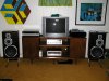
I have a near-field setup (see photo) as "MX117.MC7150" described in his post (thank you) about his experience with this amp amd some Yamaha NS-1000's. It's a small finished room in my basement. It's my understanding that the NS-1000's were designed as nearfield monitors and that's how I'm using them. I suppose they may have been designed to be be powered by V-fets like the B-1 and B-2. I've certainly read that many prefer the NS-1000's powered by tube equipment.
This could be why the TA-5650 makes a nice combination with them. It doesn't have the "grain/harsh" qualities sometimes associated with solid state, but it does convey detail and control sometimes perceived lacking in tube equipment. With all the other equipment I used I had the mids and highs dialed back on the NS-1000 pots to about -2db. As soon as I used the TA-5650 I had to turn them back up to "Normal". The mid-highs no longer seemed too "forward" in this position. The low end was also a surprise being more controlled and "real". Overall there was more detail being conveyed in sounds of individual instruments and voices. As many have described, "a veil was lifted" and the music is coming through with greater realism.
I'm sorry I'm not good at offering a description of the "soundstage", how well it "images" and the like. The bottom line is that I am impressed with this 50 watt V-fet and think it's going to be positioned right where it sits for quite some time.
As a footnote: I did go back to the (2-4) DC bias adjustment. I let the set warm-up for over an hour first then set both pots to get a 90mv reading. After this I checked the DC balance. With the longer warm-up the left channel was down to 2mv from 4 and the right channel was down to 50mv from 56-57. The next time I order from Mouser I will get the new differential pairs and follow Echowars instructions. For now, I am very pleased and enjoying beautiful music. :thmbsp: Now I'm on to a ST-4950 I found recently on the Cincinnati Craigslist to mate with the TA-5650 :yes:.
Having listened for several days now, I am very pleased with the perfomance of the TA-5650. I've had a pair of Yamaha NS-1000 speakers for a while and have to agree with "MX117.MC7150", this is the best these speakers have performed powered by the TA-5650. I've powed them with older McIntosh equipment (MX-110 & MC2105, MX-117 & MC2125), Sherwood SEL-400, and a Sherwood S-9910. None of these combinations were bad at all and some of these other pieces were not fully refurbished. Recently I added a Sony XA5400ES SACD/CD player to the mix so it's not a completely fair comparison. I've also been listening to my Sony ST-5130 tuner through the TA-5650. Man, it sounds great. One of our local college stations (WNKU, Northen KY University) has some wonderfully diverse music programing. They still make it a pleasure to listen to the radio. It's not a very powerful station, but the ST-5130 brings it in beautifully. I'm also using a Rega Planar 3 for vinyl.
I have a near-field setup (see photo) as "MX117.MC7150" described in his post (thank you) about his experience with this amp amd some Yamaha NS-1000's. It's a small finished room in my basement. It's my understanding that the NS-1000's were designed as nearfield monitors and that's how I'm using them. I suppose they may have been designed to be be powered by V-fets like the B-1 and B-2. I've certainly read that many prefer the NS-1000's powered by tube equipment.
This could be why the TA-5650 makes a nice combination with them. It doesn't have the "grain/harsh" qualities sometimes associated with solid state, but it does convey detail and control sometimes perceived lacking in tube equipment. With all the other equipment I used I had the mids and highs dialed back on the NS-1000 pots to about -2db. As soon as I used the TA-5650 I had to turn them back up to "Normal". The mid-highs no longer seemed too "forward" in this position. The low end was also a surprise being more controlled and "real". Overall there was more detail being conveyed in sounds of individual instruments and voices. As many have described, "a veil was lifted" and the music is coming through with greater realism.
I'm sorry I'm not good at offering a description of the "soundstage", how well it "images" and the like. The bottom line is that I am impressed with this 50 watt V-fet and think it's going to be positioned right where it sits for quite some time.
As a footnote: I did go back to the (2-4) DC bias adjustment. I let the set warm-up for over an hour first then set both pots to get a 90mv reading. After this I checked the DC balance. With the longer warm-up the left channel was down to 2mv from 4 and the right channel was down to 50mv from 56-57. The next time I order from Mouser I will get the new differential pairs and follow Echowars instructions. For now, I am very pleased and enjoying beautiful music. :thmbsp: Now I'm on to a ST-4950 I found recently on the Cincinnati Craigslist to mate with the TA-5650 :yes:.
Attachments

Jeff,
Besides the main filter caps, where did you order the rest of the caps from? I assume they are all radial caps also?
Thanks,
Scott
Besides the main filter caps, where did you order the rest of the caps from? I assume they are all radial caps also?
Thanks,
Scott
As promised, but not as neat as I hoped. Some values are used on more than one board so total them carefully when placing an order. *edit* I should add, this is a listing of all the ELECTROLYTIC capacitors. My listening review soon to follow...
Power Amplifier Board
µf-Volts-Quan.
470-6.3-1
100-50-2
100-35-2
47-50-2
47-10-4
10-100-2
10-50-2
Equilizer Amplifier Board
µf-Volts-Quan.
470-35-2
10-100-4
3.3-100-1
Power Supply Board
µf-Volts-Quan.
330-10-1
220-6.3-1
100-100-2
100-50-3
47-50-4
10-50-1
10-25-1
Filter Board
µf-Volts-Quan.
1000-10-2
3.3-100-4
.47-50-2
Main Filter Caps
µf-Volts-Quan.
10,000-50-2
Hi Scott,
I got all of the caps at Digikey. Yes, they are all radial. Most of them are Panasonic FC. On one value (1000uf-10V) I could get a Panasonic FM. There were two values that were out of stock on the Panasonics (.47uf-50V and 470uf-35V). For these I got Nichicon PW's (UPW). Check the Panasonics first, because IIRC that they were due in stock late this month or early next. I hope You'll enjoy your TA-5650 as much as I do mine!
I got all of the caps at Digikey. Yes, they are all radial. Most of them are Panasonic FC. On one value (1000uf-10V) I could get a Panasonic FM. There were two values that were out of stock on the Panasonics (.47uf-50V and 470uf-35V). For these I got Nichicon PW's (UPW). Check the Panasonics first, because IIRC that they were due in stock late this month or early next. I hope You'll enjoy your TA-5650 as much as I do mine!
Hello Jeff,
I now have the board out of the amp. Have taken pictures of the four diodes that need to be replaced, see attached. I just noticed the existing diodes at position 303 and 353 have two legs each. Simple fix once I decifer the correct way to wire the replacement diodes (will study your prior PM on this topic).
EDIT - Never mind the question below. I see now the diodes at at the d301 and d351 locations, not Q301 and Q351.
"The ones at 301 and 351 have three legs each. So, am unsure how the diodes at 301 and 351 should be wired using two 1N4148 replacement diodes. Please shed some light on these two locations." EDIT
Thanks,
Scott
I now have the board out of the amp. Have taken pictures of the four diodes that need to be replaced, see attached. I just noticed the existing diodes at position 303 and 353 have two legs each. Simple fix once I decifer the correct way to wire the replacement diodes (will study your prior PM on this topic).
EDIT - Never mind the question below. I see now the diodes at at the d301 and d351 locations, not Q301 and Q351.
"The ones at 301 and 351 have three legs each. So, am unsure how the diodes at 301 and 351 should be wired using two 1N4148 replacement diodes. Please shed some light on these two locations." EDIT
Thanks,
Scott
Last edited:

I am a paint-by-numbers electronics technician. As you can see, I don't know the difference between a diode and a transistor. But, can install new ones like nobody's business if guided by a steady hand and mind. 
In fact, the four new diode sets are already installed and getting ready to test it to make sure I didn't break something. Keep you fingers crossed.
EDIT - Success, the amp still plays and sounds good to my ears. Jeff and Echowars, thanks much for your help. I bought new main filter caps too, but have not installed them yet. How long to I need to leave the amp unplugged to safely work on the capacitor replacement? - EDIT
In fact, the four new diode sets are already installed and getting ready to test it to make sure I didn't break something. Keep you fingers crossed.
EDIT - Success, the amp still plays and sounds good to my ears. Jeff and Echowars, thanks much for your help. I bought new main filter caps too, but have not installed them yet. How long to I need to leave the amp unplugged to safely work on the capacitor replacement? - EDIT
Last edited:
Congratulations!
Hi Scott, Sorry I was not on the computer earlier. I'm glad Echo responded. I hope studying my previous PM was helpful in making the diode replacement a success.
To safely handle the main caps before removal I use (as advised in other Audiokarma posts) a large resistor (with leads attached that have insulated alligator clips at each end) to "bleed" the main caps. You simply clip one lead to the positive terminal and the other to the negative (doesn't matter which end of the resistor). You can observe the "drain" with your multimeter attached to each terminal and set to the "DC V" position after you've connected the resistor. Without doing this I don't know how long you would have to wait to be sure it is safe to handle them :scratch2:. Using the resistor and checking with your meter is the sure way to be safe and get to business right away. I forget the watt value of the resistor I use, but it is probably 10 watts or more. It's a 1.1 kilo ohms resistor and is about 5/16" in diameter and 15/16" long. See the photo below. Take this info to Rat Shack if you don't have a large resistor, pick one up and solder on some clips. Then you can handle them knowing you're safe without guessing :yes:.
Thanks for the photos of your v-fet devices. It looks like you're in good shape since all of yours are of the same rank. If you have time it would be a good idea to replace the mica insulators under them with new ones and some new silicone heat sink grease. Remove the V-fets, discard the old insulators, clean off the old dry grease from the devices with a paper towel, put new grease on BOTH sides of the new insulator (thin, even coat), then re-install. This will help them transfer heat to the heat sink more effectively prolonging their life. Happy listening!
Hi Scott, Sorry I was not on the computer earlier. I'm glad Echo responded. I hope studying my previous PM was helpful in making the diode replacement a success.
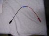
To safely handle the main caps before removal I use (as advised in other Audiokarma posts) a large resistor (with leads attached that have insulated alligator clips at each end) to "bleed" the main caps. You simply clip one lead to the positive terminal and the other to the negative (doesn't matter which end of the resistor). You can observe the "drain" with your multimeter attached to each terminal and set to the "DC V" position after you've connected the resistor. Without doing this I don't know how long you would have to wait to be sure it is safe to handle them :scratch2:. Using the resistor and checking with your meter is the sure way to be safe and get to business right away. I forget the watt value of the resistor I use, but it is probably 10 watts or more. It's a 1.1 kilo ohms resistor and is about 5/16" in diameter and 15/16" long. See the photo below. Take this info to Rat Shack if you don't have a large resistor, pick one up and solder on some clips. Then you can handle them knowing you're safe without guessing :yes:.
Thanks for the photos of your v-fet devices. It looks like you're in good shape since all of yours are of the same rank. If you have time it would be a good idea to replace the mica insulators under them with new ones and some new silicone heat sink grease. Remove the V-fets, discard the old insulators, clean off the old dry grease from the devices with a paper towel, put new grease on BOTH sides of the new insulator (thin, even coat), then re-install. This will help them transfer heat to the heat sink more effectively prolonging their life. Happy listening!
Attachments
Jeff,
Thanks for the capacitor bleed advice. Will check my box of electronics and see what size resistors I have on hand.
Where could a person find the mica insulators you mention? What kind of grease should be used?
Am thinking the bias and offset should be checked too. I'll proceed carefully on that though. Already messed up one amp doing this check. Will look in the service manual you sent for guidance.
Thanks,
Scott
Thanks for the capacitor bleed advice. Will check my box of electronics and see what size resistors I have on hand.
Where could a person find the mica insulators you mention? What kind of grease should be used?
Am thinking the bias and offset should be checked too. I'll proceed carefully on that though. Already messed up one amp doing this check. Will look in the service manual you sent for guidance.
Thanks,
Scott
I'm sure Digikey and Mouser have these. You are looking for Mica insulators for "TO-3" (this is the case type) transistors. I get mine from MCM: www.mcmelectronics.com because they are so close to me (no affiliation). They are also closer to you than Mouser or Digikey. MCM part #21-1165 for the insulators (be aware: ordering 1 gets you a pack of 25). The grease is part #20-300. It is called "silicone heat sink compound". Glad to help. Studying the service manual is good practice. The more you look at it the more will make sense and you'll begin to understand the symbols. Soon you'll know what different devices look like and what the symbols and values for them mean in the schematics. Believe me, I am not that far ahead of you on the learning curve!
Jeff, thanks much for the guidance. I replaced the main filter caps today and the FET transistor micas/grease. Being a newb, I didn't realize the filter caps are polar and got one oriented incorrectly. When I powered it on, it blew the two 6.3 amp fuses on the rectifier board. Looked at one of your pictures and oriented both caps in the same direction (writing facing the front of amp) and installed new 5 amp fuses (always go smaller, not larger, if you don't have an exact replacement, don't ask me how I learned this!!).
She's now playing fine and I'm checking the DC offset using Echowars instructions. Looks like the left channel DC offset is 40 mV and the right is 8.5 mV. Do I need to adjust anything?
EDIT - I went ahead and made all four measurement/adjustments called out in the manual (20V, 100V, bias and offset). - EDIT
She's now playing fine and I'm checking the DC offset using Echowars instructions. Looks like the left channel DC offset is 40 mV and the right is 8.5 mV. Do I need to adjust anything?
EDIT - I went ahead and made all four measurement/adjustments called out in the manual (20V, 100V, bias and offset). - EDIT
Last edited:
Am guessing you did not really set them at 20V & 100V. :nono:Looks like the left channel DC offset is 40 mV and the right is 8.5 mV. Do I need to adjust anything?
EDIT - I went ahead and made all four measurement/adjustments called out in the manual (20V, 100V, bias and offset). - EDIT
No adjustment
Hi Scott, Sorry you had that trouble. We all make mistakes. As far as caps go, most will be polar. Non-polar ones will be the exceptions not the rule. At least the fuses did their jobs and saved you from tradgedy!
There is no adjustment for the "DC offset". Refer to my post #20, Echowars post #22 and my post #23 in this thread. Even though measuring the DC balance (2-3) is in the adjustment section there is no adjustment. As it says, you are only confirming it measures between 0-50mv. You are within specification. The only thing you may want to do is find the correct value fuses when you get the chance. Congratulations, you should have a fine sounding amp and now it is much more likely to have a longer life!
In the posts to which I've referred you, Echowars explains that the only way to improve (lower the millivolts and have the channels more closely matched) is to replace the "differential pairs" of transistors for each channel on the power amplifier board with "matching" pairs. I'm going to do this to mine in the not-too-distant future. I will post about this when I do it and have some time. I have already purchased 25 of them and have started to measure them for gain (hfe). The idea here is to install replacements that are closely matched in measured gain (hfe).
MX-117.MC7150: Scott is correct about what he is stating for these values (20v and 100v). He is reffering to Section 2 of the service manual "Adjustment". 20v is the spec. for section 2-1 and 97v (+or -3v) is the spec. for section 2.2. See page 5 of the servive manual.
Hi Scott, Sorry you had that trouble. We all make mistakes. As far as caps go, most will be polar. Non-polar ones will be the exceptions not the rule. At least the fuses did their jobs and saved you from tradgedy!
There is no adjustment for the "DC offset". Refer to my post #20, Echowars post #22 and my post #23 in this thread. Even though measuring the DC balance (2-3) is in the adjustment section there is no adjustment. As it says, you are only confirming it measures between 0-50mv. You are within specification. The only thing you may want to do is find the correct value fuses when you get the chance. Congratulations, you should have a fine sounding amp and now it is much more likely to have a longer life!
In the posts to which I've referred you, Echowars explains that the only way to improve (lower the millivolts and have the channels more closely matched) is to replace the "differential pairs" of transistors for each channel on the power amplifier board with "matching" pairs. I'm going to do this to mine in the not-too-distant future. I will post about this when I do it and have some time. I have already purchased 25 of them and have started to measure them for gain (hfe). The idea here is to install replacements that are closely matched in measured gain (hfe).
MX-117.MC7150: Scott is correct about what he is stating for these values (20v and 100v). He is reffering to Section 2 of the service manual "Adjustment". 20v is the spec. for section 2-1 and 97v (+or -3v) is the spec. for section 2.2. See page 5 of the servive manual.