• The move to the new server is done. There are some software and database maintenance updates in process. This has us passing the hat around to help out. We appreciate any donations. Seriously, even a dollar helps. The payment page may be found here - https://www.audiokarma.org/support.html

Sony TA-F3A Bias adjustment

mariuss

New Member
Hello, I got a defective TA-F3A from a friend who got sick of having to fix the left channel by replacing the power\final-stage transistors (Q706 & 707)!
The right channel has no issues, all original components work fine, bias is adjustable to the recommended value, 8-10mV.
Here is the info for left channel:
- DC balance works fine, I was able to set it to 0V
- replaced power caps with 10000uF/80V
- I replaced Q706 & 707 with MJE15032G\MJE15033G
- I replaced D701 with 2 x 1N4148 in series
- replaced all the electrolytic caps (all old ones tested good, but)
- replaced RV 702
- replaced all fusible and power resistors (2 x 120ohm, 2 x 22ohm & 2 x 0.22ohm 5W)
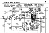
When I power up the amp and measure bias voltage over R716 (0.22ohm on the emitter of power transistor) it reads right away over 100mv and increasing slowly to over 220mv, and the power transistors and fusible resistors get fried. Adjusting RV702 has almost no effect. I don't have a replacement for Q703 (2SC1940L0 to try to replace it, but this is my last hope for fixing this amp.
Anyone can help me with some advice on how to move forward?
upload_2019-12-9_12-36-56.png
 
Last edited:
Register to hide this ad
Looks like you are having a thermal runway, that means the bias network is not doing it's job. The bias network should keep Q704-Q705 bases at a close voltage. If temperature raises, D701 is supposed to conduct more, lowering the voltage between Q704-Q705. In theory, a short circuit between Q704-Q705 bases should reduce the bias to zero. And an open circuit between Q704-Q705 bases (D701 not conducting, damaged, R710 open, RV702 open or with a very high resistance) would raise the bias and burn the output.

Check the fuse resistors R712 to R715, ( I read 150 ohm not 120) , check Q703 or replace it (any transistor with similar specs will work), check all the components around RV702 and the DIY diode you made. You need current flowing through the diode-resistor network, and that current flow comes from R708, R709 and goes to Q703-R711. Your problem suggest me that you are not having the right voltage drop at RV702, current not flowing, some open circuit in that network.

Suspect of that 2 x 1N4148 you built. check it again, verify the voltage drop across the dual diode. Perhaps you need a lower voltage drop (I use 3 x 1N4148 to replace the STV-4H diodes, not 4 x 4148 since the voltage drop of each single diode is a bit higher than the original)

Use a DBT to test the amp, if bias increases quickly, shut down the amp, it won't fix by itself.

I wouldn't give up yet, the output is very simple, redoing from scratch will work.
 
Thank you Elnado, you are right, it is 150ohm, and that is what I used. I have measured the voltage on Q704/705 base and it is 0.65/-0.65V, and that made me think that R708/709 are OK, but I'll replace those two and see if it helps.
I am waiting for a replacement for Q703 and after replacing it I'll try again to see if it works.
I'll post the results here after testing.
 
What I always do to test bias runaway issues is replace the emitter resistors (in this case R716/7) with higher value ones. Around 100R/3W is perfect. In the fault condition your output transistors don't get fried this way. When you have found your problem the amp works (albeit unable to provide any useful power). BTW- if R713/4 are wrong value (too low, should be 22R) you can get the symptom you experience. But it looks like yours are correct...

Tjerk, 9ZZ
 
I am not getting anywhere with this issue! I might be blind, but I cannot find out where is the fault in this.
I have removed all the components on the power amp board for this channel, none of those were faulty (I tested them after removal), but I replaced them anyway thinking that these transistors are old and might misbehave when under power\load. As Tjerk suggested I used 110R for R716/7 and measured all the test points voltages, compared with the measurements from the other channel and are very close or identical with the ones marked in the service manual. I can even get decent output with the 110R resistors! But, the moment I replaced R716/717 with 0.22R the output transistors blow, literally!
I did check the speaker relay and everything after it to see if there is a short somewhere, but I cannot find anything, and as I said, I can get decent output with 110R resistors in, so I think there is nothing at fault after output transistors.
I think I need a fresh pair of eyes to look at this because I was looking at it too much and I might no be able to see something obvious. If anyone has more ideas, please let me know.
Thank you all.
 

Attachments

  • ta-f3a.JPG
    ta-f3a.JPG
    121.1 KB · Views: 29
That's a rather strange bias network. If you set RV702 near it's minimum resistance, you should be able to totally turn the output stage off. If you can't there is something in one of the Sziklai pairs in the output. Increasing the resistance of RV702 should bring on some idle current. It's almost as if the 2 diodes and the 22 ohm resistor are there only as a safety limit if you adjust the pot too high. Not a lot of thermal compensation.

If it comes on suddenly, you may have an issue with oscillation. Sziklai pairs are prone to this, and if you replaced the original parts with faster parts, this is quite possible the problem. Add a 220 pF cap between the base and collector of Q705.
 
I tried what Ylli suggested, but no luck, it actualy made adjusting DC Balance imposible, I can no longer get to 0V DC, it hovers arround 600mV now.
 
Does it return to the original condition if you remove the cap? That would still be an indication of oscillation, but the cap was not an effective fix.
 
It doesn't return to original condition after removing the cap! And what is more strange, now (after removing the cap) Q705 is getting hot in 30-50s after powering the unit ON. It did not do that before. I still have 110R for R716/7, did not have courage to change them to 0.22R yet. I am sure it will blow the output transistors if I do. I checked the output with my scope and can not see any oscilation on the output, with no input signal. Am I checking oscilation at the wrong point?
 
Forgot to mention, the amp still works, I can hear the music on both channels. I also compared what "noise" the scope shows on both chnnels, with no input signal, and it looks the same for both.
 
Sounds like we may have damaged one of the transistors. You did use a 220 pF, and not a 220 uF, right? The cap should not have caused that to happen.
 
Maybe an obvious "just in case", but have you checked for proper isolation between the driver transistors and the heat sink? And for the D701 replacement as well?
 
Yes, I did that, no issues there, D701 replacement is wrapped in a shrink tube. The issue is that I don't think D701 has enough time to do anything, the driver transistors blow the moment I power up the amp if the 0.22R are in place.
 
Yes, I did that, no issues there, D701 replacement is wrapped in a shrink tube. The issue is that I don't think D701 has enough time to do anything, the driver transistors blow the moment I power up the amp if the 0.22R are in place.

Then It might be interesting to weld a wire on to those zenners, and "electronically" switch them between left and right, while keeping them physically in the same place. That way you could rule out any defect in the zenners.
 
What is the bias voltage across the emitter resistors when you use 110 ohm as emitter resistors? Something must be indicating an excessive current capable of blowing the output when you fit the 0.22R

Instant blow to me means a direct short. I'd disconnect everything from the output, (I'm thinking to remove R718, R720, Speaker selector board, and any wiring or anything from the junction of Q706 Q707. And check for any possible physical short (solder bridges, wires pressed with a screw, bare wires touching something)

Did you identify which transistor blows first? In post #6 you mention Outputs, in post #16 you mention Drivers. In any case, see if just one is blown, which one.

Please check the fuse resistors again.

Are you using a DBT ?? It should save the transistors from a short circuit.

BTW, the times I've received units blowing transistors, usually the fault was direct shorts, solder bridges or wires not seen by the previous tech. A pict of the solder side of your board could be helpful. If you see your soldering work is very polite, please disregard this suggestion.
 
Last edited:
To answer Elnaldo's questions first:
- the bias voltage over 110R was from 0.1V to 1V, going up and down all the time, without any signal on the input and volume at zero.
- Q707 was the transistor that blew first, and it took Q706 with it. I always checked the damn fuse resistors, I decreased those to 1/4W to make sure they blow and protect the Output transistors, but no luck with that!
- Sorry, I meant the Output transistors.
- I did not use a DBT, is at work and I am home on holiday.

Here is an, hopefully positive, update:
- Q705 was damaged, so I replaced it (Ylli please do not feel bad, I appreciate your help!) and removed the 220p cap.
- I disconnected everything after the Output junction, the wires going to Speakers board, the Zobel network resistor R718 (checked the cap C709 too) and the resistor R720 going to the speaker protection circuit. I checked all the wires with my ohmmeter and did not find any shorts. I visually inspected everything and everything looks fine.
- Powered up the amp and to my surprise, everything looks perfect, the bias voltage over the 110R resistor is stable and I was able to adjust it from RV702 to 0.06V and I was able to adjust DC to 0V.
- Connected the speaker wires, no issues with voltage measurements. The only thing that was not OK, I think I got some oscillation after disconnecting R718, every once in a while I could hear some "popping sound" in the speaker.
- Connected back R718, no issues, and no more popping sound
- Connected back R720, no issues again

Now I am waiting to get enough courage to put the 0.22R resistors back and hope to not blow the Output transistors again. I ran the amp with 110R for an hour, with input signal, and the only thing I noticed is that Q704&705 get warmer.
 
Back
Top Bottom