goat67
Addicted Member
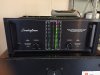
This thread is a place for information on servicing Soundcraftsmen Class H Amps
Models:
First Generation (These amps utilize a quasi-complementary output stage)
MA5002
EA5003
PA5001
Second Generation (Home Models)
MA5002A
PA5001A
(Professional Models)
RA7500 series
RA6501
I have been working on a few things around these. So I thought it might be a good Idea to create this thread and consolidate the info I have posted and others in the past.
I by no means know all there is to know about these amps but I have done a fair bit of research and have repaired a few of them.
So some basic info to start.....
MA5002 VU Meters and AB Speaker Selector
EA5003 Equalizer Amp (EA) add an Equalizer No Meters
PA5001 No Meters No Speaker Selector
Power Output 250 Watts 8 Ohms 360 Watts 4 Ohms
Internal info Circuit boards connected using point to point wire wrap connections.
Circuit boards
Power Supply / Protection
PreDriver
No DC Offset adjust must correct by matching diff pair transistors use Zetex ZTX694B
Output Driver Board Transistors used per chan
6 2SD665 marked 8 for later models
or
6 Toshiba 2SD424 for earlier models marked 4
1 Fairchild 2N6285 PNP Darlington marked 25
1 Fairchild 2N6282 NPN Darlington marked 26
+++++++++++++++++++++++++++++++++++++++++++++++++++++++++
Second Generation (Home Models)
MA5002A LEDS and AB Speaker Selector
PA5001A No LEDS No Speaker Selector
Power Output 250 Watts 8 Ohms 375 Watts 4 Ohms
Professional Series RA7501 RA7502 RA7503 RA6501
Bridged Mono Mode supported
Balanced unbalanced Inputs
RA7501 Gain Controls and Clip Indicator
RA7502 Gain Controls Vari-portional Ind Clip Indicator and Power LEDS
RA7503 Gain Controls Vari-portional Ind Clip Indicator and Power LEDS Eq LEDS
RA6501 Same as RA7501 but without balanced Line No Bridged Mode No Gain Controls
Power Output Bridged Mono 750 Watts 8 Ohms
Stereo 250 Watts 8 Ohms 375 Watts 4 Ohms
The Internal construction changed to use molex connectors for interconnects between circuit boards same boards used between series
Circuit boards
Power Supply / Protection
Same board used on PA5001A MA5002A RA7501 RA7502 RA7503 RA6501
PreDriver
No DC Offset adjust must correct by matching transistors
Same board used on PA5001A MA5002A RA7501 RA7502 RA7503 RA6501
Output Driver Board Transistors used per chan
*4 Toshiba 2SD665 marked 8
*4 Toshiba 2SB645 marked 5
1 Fairchild 2N6285 PNP Darlington marked 25
1 Fairchild 2N6282 NPN Darlington marked 26
* Note PA5001A and MA5502A have only 3
Input Board used on RA series only
Here is a great thread on adjusting DC offset by changing the value of R4
Also a detailed explanation of the theory of the Offset circuit.
http://www.audiokarma.org/forums/showthread.php?t=214278
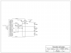
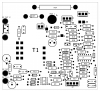
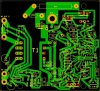
Here is a power supply board from a RA7502. I renumbered the components so use the following three images.


Power Supply BOM
C1 .1uf
C2 470uf
C3 .1uf
C4 .22uf
C5 .047uf
C6 .01uf
C7 .1uf
C8 .01uf
C9 .22uf
C10 .027uf
C11 4.7uf
C12 .1uf
CR1 1N4005
CR2 1N4005
CR3 1N4742 12v Zener
CR4 1N4005
CR5 1N4005
CR6 1N4005
CR7 1N4005
CR8 1N4005
CR9 MR751
CR34-37 1N4005
F1 10A
J1 AC IN
J2 Power and Overload Leds
J3 Ch 1 Thermal Overload
J4 Ch 2 Thermal Overload
J5 To Power Transformer
J7 +- 93vdc
J8 To board 5G1 5G2 Over Current Sense
Q1 BC239C
Q2 BC309C
Q3 BC239C
Q4 BC239C
R1 120
R2 2.7K
R3 30
R4 10K
R5 150K
R6 100K
R7 1M
R8 220K
R9 470
R10 2.2K
R11 15M
R12 47K
R13 22
R14 3.3K
R15 4.7K
R16 1K
R17 10K
R18 15M
R19 4.7K
R20 33K
R21 10K
R22 75K
R23 100K
R24 1M
R25 10K
R26 100K
R27 2.7K
R28 1M
R29 2.5M
R30 1.3K
R31 1.3K
R32 120
R33 91
R34 1 10W
R35 120
SCR SIPS325
SW Power Switch
T1 12v Pwr supply Transformer
TR1 IT415
U1 LM3900
U2 H11C3
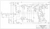
Schematics for Pre Driver Board MA5002

BOM MA5002
C1 25uf NP
C2 330pf
C3 22pf
C4 22pf
C5 10pf Rev A Only
C6 220uf
C7 .1uf
C8 10uf
C9 .1uf
C10 10uf
C11 .047
C12 470pf
C13 470pf
C14 2.2uf
C15 47uf
C16 .027uf
C17 .47uf
C18 .1uf
C19 .027uf
C20 .47uf
CR1 1N4148
CR2 1N4148
CR3 1N4148
CR4 1N4148
CR5 1N4148
CR6 1N4148
CR7 1N4148
CR8 1N4148
CR9 1N4148
CR10 1N4005
CR11 1N4005
CR12 Red Clip
CR13 1N4005
CR14 MR751
CR15 1N4148
CR16 1N4148
CR17 MR751
CR18 1N4005
CR19 Green
CR20 MR751
CR21 MR751
J1 Input
L1 .2 uh
Q1 MPSL01
Q2 MPSL01
Q3 MPSL01
Q4 2N3440
Q5 MM4003
Q6 2N3403
Q7 MPSL01
Q8 2N3440
Q9 MPSA93
Q10 MM4003
Q11 2SD665
Q12 2SD665
Q13 2SD665
Q14 2SD665
Q15 2SD665
Q16 2SD665
Q17 MPSA93
Q18 MPSA93
Q19 2N6285
Q20 MPSA93
Q21 MPSL01
Q22 MPSA93
Q23 MPSL01
Q24 2N6282
Q25 MPSA93
Q26 MPSL01
R1 50K
R2 150K
R3 2.2K
R4 68K
R5 1K
R6 22K
R7 2.2K
R8 10
R9 390
R10 620
R11 22K
R12 22
R13 1.3K
R14 330
R15 500
R16 22K
R17 120
R18 300
R19 10K
R20 22K
R22 22K
R23 10K
R24 22
R25 120
R26 22
R27 120
R28 10
R29 10
R30 .27
R31 .27
R32 .27
R33 .27
R34 .27
R35 470
R36 470
R37 270
R38 180
R39 150K
R40 3.3K
R42 300
R43 2.2K
R44 10K
R45 10K
R46 300
R47 2.2K
R48 5 5W
R49 10K
R50 10K
R51 1K
R52 120
R53 1
R54 10K
R55 120
R56 1
R96 300
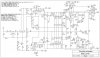
Schematic for Pre Driver Board RA7500
NOTE Bias setting is wrong adjust to 2.5 to 3mv I will update Schematic when it is ready

BOM RA7500
C1 25uf NP
C2 330pf
C3 22pf
C4 22pf
C6 220uf
C7 .1uf
C8 10uf
C9 .1uf
C10 10uf
C11 4.7uf
C12 4.7uf
C13 2.2uf
C14 .0068uf
C15 .0068uf
C16 .001UF
C17 .001UF
C19 .1uf
C21 .47uf
C22 .47uf
C23 47uf
C24 150pf
C25 470pf
CR1 1N4150
CR2 1N4150
CR3 1N4150
CR4 1N4150
CR5 1N4150
CR6 1N4150
CR7 1N4150
CR8 1N4150
CR9 1N4150
CR10 1N4150
CR11 1N3070
CR12 1N4150
CR13 1N4150
CR14 1N4150
CR15 1N3070
CR16 1N4150
CR17 1N4150
CR18 1N4150
CR19 1N4150
CR20 1N4150
CR21 1N3070
CR22 1N3070
CR23 MR751
CR24 MR751
CR25 1N4005
CR26 1N4005
CR27 MR751
CR28 1N4005
CR29 MR751
CR30 Green
CR43 1N4150
CR45 Red Clip
J1 Input
L1 .4 uh
Q1 MPSL01
Q2 MPSL01
Q3 MPSL01
Q4 2N3440
Q5 MM4003
Q6 2N3417
Q7 MPSL01
Q8 2N3440
Q9 MPSA93
Q10 MM4003
Q11 2SD665
Q12 2SD665
Q13 2SD665
Q14 2SB645
Q15 2SB645
Q16 2SB645
Q17 MPSL01
Q18 MPSA93
Q19 MPSL01
Q20 MPSA93
Q21 MPSA93
Q22 MPSA93
Q23 MPSL01
Q24 MPSA93
Q25 MPSL01
Q26 MPSL01
Q27 MPSA93
Q28 MPSA93
Q29 2N6285
Q30 2N6282
Q36 2SD665
Q37 2SB645
Q38 MPSA93
R1 1K
R2 2.2K
R3 68K
R4 1K
R5 2.2K
R6 22K
R7 390
R8 47
R9 22K
R10 620
R11 22K
R12 120
R13 91
R14 10K
R15 1.3K
R16 210
R17 100
R18 10K
R19 91
R20 10K
R21 22K
R22 22K
R23 10K
R24 3.3K
R25 22K
R26 91
R27 91
R28 10
R29 3.3K
R30 270
R31 15K
R32 1K
R33 10
R34 620
R35 1.3K
R36 1K
R37 470
R38 10K
R39 91
R40 91
R41 10K
R42 470
R43 2.7K
R44 10K
R45 10K
R46 10K
R47 10K
R48 2.7K
R49 620
R50 620
R51 120
R52 5 5W
R53 300
R54 220
R55 620
R56 120
R57 1
R58 10K
R59 1
R60 1K
R61 10
R62 .27
R63 .27
R64 .27
R65 10
R66 .27
R67 .27
R68 .27
R122 10
R123 .27
R124 .27
R125 10K
R126 100K
R127 120

Latest version

Models:
First Generation (These amps utilize a quasi-complementary output stage)
MA5002
EA5003
PA5001
Second Generation (Home Models)
MA5002A
PA5001A
(Professional Models)
RA7500 series
RA6501
I have been working on a few things around these. So I thought it might be a good Idea to create this thread and consolidate the info I have posted and others in the past.
I by no means know all there is to know about these amps but I have done a fair bit of research and have repaired a few of them.
So some basic info to start.....
MA5002 VU Meters and AB Speaker Selector
EA5003 Equalizer Amp (EA) add an Equalizer No Meters
PA5001 No Meters No Speaker Selector
Power Output 250 Watts 8 Ohms 360 Watts 4 Ohms
Internal info Circuit boards connected using point to point wire wrap connections.
Circuit boards
Power Supply / Protection
PreDriver
No DC Offset adjust must correct by matching diff pair transistors use Zetex ZTX694B
Output Driver Board Transistors used per chan
6 2SD665 marked 8 for later models
or
6 Toshiba 2SD424 for earlier models marked 4
1 Fairchild 2N6285 PNP Darlington marked 25
1 Fairchild 2N6282 NPN Darlington marked 26
+++++++++++++++++++++++++++++++++++++++++++++++++++++++++
Second Generation (Home Models)
MA5002A LEDS and AB Speaker Selector
PA5001A No LEDS No Speaker Selector
Power Output 250 Watts 8 Ohms 375 Watts 4 Ohms
Professional Series RA7501 RA7502 RA7503 RA6501
Bridged Mono Mode supported
Balanced unbalanced Inputs
RA7501 Gain Controls and Clip Indicator
RA7502 Gain Controls Vari-portional Ind Clip Indicator and Power LEDS
RA7503 Gain Controls Vari-portional Ind Clip Indicator and Power LEDS Eq LEDS
RA6501 Same as RA7501 but without balanced Line No Bridged Mode No Gain Controls
Power Output Bridged Mono 750 Watts 8 Ohms
Stereo 250 Watts 8 Ohms 375 Watts 4 Ohms
The Internal construction changed to use molex connectors for interconnects between circuit boards same boards used between series
Circuit boards
Power Supply / Protection
Same board used on PA5001A MA5002A RA7501 RA7502 RA7503 RA6501
PreDriver
No DC Offset adjust must correct by matching transistors
Same board used on PA5001A MA5002A RA7501 RA7502 RA7503 RA6501
Output Driver Board Transistors used per chan
*4 Toshiba 2SD665 marked 8
*4 Toshiba 2SB645 marked 5
1 Fairchild 2N6285 PNP Darlington marked 25
1 Fairchild 2N6282 NPN Darlington marked 26
* Note PA5001A and MA5502A have only 3
Input Board used on RA series only
Here is a great thread on adjusting DC offset by changing the value of R4
Also a detailed explanation of the theory of the Offset circuit.
http://www.audiokarma.org/forums/showthread.php?t=214278
Here is a power supply board from a RA7502. I renumbered the components so use the following three images.
Power Supply BOM
C1 .1uf
C2 470uf
C3 .1uf
C4 .22uf
C5 .047uf
C6 .01uf
C7 .1uf
C8 .01uf
C9 .22uf
C10 .027uf
C11 4.7uf
C12 .1uf
CR1 1N4005
CR2 1N4005
CR3 1N4742 12v Zener
CR4 1N4005
CR5 1N4005
CR6 1N4005
CR7 1N4005
CR8 1N4005
CR9 MR751
CR34-37 1N4005
F1 10A
J1 AC IN
J2 Power and Overload Leds
J3 Ch 1 Thermal Overload
J4 Ch 2 Thermal Overload
J5 To Power Transformer
J7 +- 93vdc
J8 To board 5G1 5G2 Over Current Sense
Q1 BC239C
Q2 BC309C
Q3 BC239C
Q4 BC239C
R1 120
R2 2.7K
R3 30
R4 10K
R5 150K
R6 100K
R7 1M
R8 220K
R9 470
R10 2.2K
R11 15M
R12 47K
R13 22
R14 3.3K
R15 4.7K
R16 1K
R17 10K
R18 15M
R19 4.7K
R20 33K
R21 10K
R22 75K
R23 100K
R24 1M
R25 10K
R26 100K
R27 2.7K
R28 1M
R29 2.5M
R30 1.3K
R31 1.3K
R32 120
R33 91
R34 1 10W
R35 120
SCR SIPS325
SW Power Switch
T1 12v Pwr supply Transformer
TR1 IT415
U1 LM3900
U2 H11C3
Schematics for Pre Driver Board MA5002
BOM MA5002
C1 25uf NP
C2 330pf
C3 22pf
C4 22pf
C5 10pf Rev A Only
C6 220uf
C7 .1uf
C8 10uf
C9 .1uf
C10 10uf
C11 .047
C12 470pf
C13 470pf
C14 2.2uf
C15 47uf
C16 .027uf
C17 .47uf
C18 .1uf
C19 .027uf
C20 .47uf
CR1 1N4148
CR2 1N4148
CR3 1N4148
CR4 1N4148
CR5 1N4148
CR6 1N4148
CR7 1N4148
CR8 1N4148
CR9 1N4148
CR10 1N4005
CR11 1N4005
CR12 Red Clip
CR13 1N4005
CR14 MR751
CR15 1N4148
CR16 1N4148
CR17 MR751
CR18 1N4005
CR19 Green
CR20 MR751
CR21 MR751
J1 Input
L1 .2 uh
Q1 MPSL01
Q2 MPSL01
Q3 MPSL01
Q4 2N3440
Q5 MM4003
Q6 2N3403
Q7 MPSL01
Q8 2N3440
Q9 MPSA93
Q10 MM4003
Q11 2SD665
Q12 2SD665
Q13 2SD665
Q14 2SD665
Q15 2SD665
Q16 2SD665
Q17 MPSA93
Q18 MPSA93
Q19 2N6285
Q20 MPSA93
Q21 MPSL01
Q22 MPSA93
Q23 MPSL01
Q24 2N6282
Q25 MPSA93
Q26 MPSL01
R1 50K
R2 150K
R3 2.2K
R4 68K
R5 1K
R6 22K
R7 2.2K
R8 10
R9 390
R10 620
R11 22K
R12 22
R13 1.3K
R14 330
R15 500
R16 22K
R17 120
R18 300
R19 10K
R20 22K
R22 22K
R23 10K
R24 22
R25 120
R26 22
R27 120
R28 10
R29 10
R30 .27
R31 .27
R32 .27
R33 .27
R34 .27
R35 470
R36 470
R37 270
R38 180
R39 150K
R40 3.3K
R42 300
R43 2.2K
R44 10K
R45 10K
R46 300
R47 2.2K
R48 5 5W
R49 10K
R50 10K
R51 1K
R52 120
R53 1
R54 10K
R55 120
R56 1
R96 300
Schematic for Pre Driver Board RA7500
NOTE Bias setting is wrong adjust to 2.5 to 3mv I will update Schematic when it is ready
BOM RA7500
C1 25uf NP
C2 330pf
C3 22pf
C4 22pf
C6 220uf
C7 .1uf
C8 10uf
C9 .1uf
C10 10uf
C11 4.7uf
C12 4.7uf
C13 2.2uf
C14 .0068uf
C15 .0068uf
C16 .001UF
C17 .001UF
C19 .1uf
C21 .47uf
C22 .47uf
C23 47uf
C24 150pf
C25 470pf
CR1 1N4150
CR2 1N4150
CR3 1N4150
CR4 1N4150
CR5 1N4150
CR6 1N4150
CR7 1N4150
CR8 1N4150
CR9 1N4150
CR10 1N4150
CR11 1N3070
CR12 1N4150
CR13 1N4150
CR14 1N4150
CR15 1N3070
CR16 1N4150
CR17 1N4150
CR18 1N4150
CR19 1N4150
CR20 1N4150
CR21 1N3070
CR22 1N3070
CR23 MR751
CR24 MR751
CR25 1N4005
CR26 1N4005
CR27 MR751
CR28 1N4005
CR29 MR751
CR30 Green
CR43 1N4150
CR45 Red Clip
J1 Input
L1 .4 uh
Q1 MPSL01
Q2 MPSL01
Q3 MPSL01
Q4 2N3440
Q5 MM4003
Q6 2N3417
Q7 MPSL01
Q8 2N3440
Q9 MPSA93
Q10 MM4003
Q11 2SD665
Q12 2SD665
Q13 2SD665
Q14 2SB645
Q15 2SB645
Q16 2SB645
Q17 MPSL01
Q18 MPSA93
Q19 MPSL01
Q20 MPSA93
Q21 MPSA93
Q22 MPSA93
Q23 MPSL01
Q24 MPSA93
Q25 MPSL01
Q26 MPSL01
Q27 MPSA93
Q28 MPSA93
Q29 2N6285
Q30 2N6282
Q36 2SD665
Q37 2SB645
Q38 MPSA93
R1 1K
R2 2.2K
R3 68K
R4 1K
R5 2.2K
R6 22K
R7 390
R8 47
R9 22K
R10 620
R11 22K
R12 120
R13 91
R14 10K
R15 1.3K
R16 210
R17 100
R18 10K
R19 91
R20 10K
R21 22K
R22 22K
R23 10K
R24 3.3K
R25 22K
R26 91
R27 91
R28 10
R29 3.3K
R30 270
R31 15K
R32 1K
R33 10
R34 620
R35 1.3K
R36 1K
R37 470
R38 10K
R39 91
R40 91
R41 10K
R42 470
R43 2.7K
R44 10K
R45 10K
R46 10K
R47 10K
R48 2.7K
R49 620
R50 620
R51 120
R52 5 5W
R53 300
R54 220
R55 620
R56 120
R57 1
R58 10K
R59 1
R60 1K
R61 10
R62 .27
R63 .27
R64 .27
R65 10
R66 .27
R67 .27
R68 .27
R122 10
R123 .27
R124 .27
R125 10K
R126 100K
R127 120
Latest version
Last edited: