
• The move to the new server is done. There are some software and database maintenance updates in process. This has us passing the hat around to help out. We appreciate any donations. Seriously, even a dollar helps. The payment page may be found here - https://www.audiokarma.org/support.html

Soundcraftsmen RA7502 Project

jhs_61

Member
In starting this thread, I would like to recognize that the amount of Soundcraftsmen information on this site is amazing. Goat67, Avionic, and Geode have provided massive amounts of information/guidance in dozens of threads that I have sincerely enjoyed. I have owned Soundcraftsmen products my entire adult life and consider the sound to be truly exceptional. I recently purchased an RA7502 with a “D” serial number that was not working. The case/faceplate were cosmetically better than expected and I thought it might be an extraordinary learning opportunity. Frankly, I was very excited by the opportunity to troubleshoot it and bring it back to life. In the past two months, I have totally rebuilt both pre-driver boards, including all transistors, diodes, resistors, etc. I also replaced the output transistors with On-semis, and two of the emitter resistors. I replaced the volume pots, replaced the SCR and Triac on the PS board, replaced all electrolytic capacitors throughout the amp. The main caps were replaced with 39K uf and 18K uf units.

After checking, double checking and rechecking with a level of extreme paranoia, the moment of truth had finally come. Dummy loads, and an iPhone with a tone generator were connected and volume levels were turned to zero. I connected two multimeters, one across the speaker terminals and one across 2A4 and 3B4 and turned the amp on. The protect light immediately illuminated and after about a second the green LEDs jumped on both sides equally and the protect light went off. I also have an RA7502 “BW” serial number that is fully functional and it does not do that. Only the green LEDs jump. The amp also had a slightly loud transformer hum that was greatly reduced when I adjusted the trim pots on the pre-driver board. I can only adjust the trim pots to >20mv and that is a concern as well. The DC offset on both channels is -25mv and 28mv even after matching the input transistors. I turned the volume up on the iPhone and adjusted the “A” channel volume pot and there was no change in output at the speaker terminals. Same thing for channel “B”. I replaced the TL072CP chip on the input board with a TLE2072CP and there was no change. I removed the pre-driver boards and rechecked them and cannot find my error. Voltage at the main caps is 92v and 62v, which is also present at the four-pin connector on the pre-driver boards in correct order with inverse voltages as well. I am at a point of uncertainty and any help/advice would be greatly appreciated. I have attached some pictures and schematics in an effort to assist. Thank you!
 

Attachments
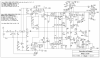
  • predriverRA_200dpi_new.png
    predriverRA_200dpi_new.png
    188.1 KB · Views: 62
Last edited:
Register to hide this ad
Yes, 428th AMU 1980 - 1983, Avionics Specialist, we have a lot in common. I'm trying to upload attachments, but they are too large, any advice?
 
Last edited:
I was a Gunsmoke participant in 1983, really enjoyed my time in the AF. Nellis was a great experience. I did get a TDY to Bentwaters, 42 days, but all CONUS other than that. Great dedicated people, made me proud!
 
This evening I once again attempted to adjust the bias voltage. I attached the leads to my multi-meter to board 2 pin A4 and board 3 pin B4. I am getting -62.5 volts on channel A and 62.5 volts on channel B and I know this does not compute. I have not applied any input signal yet and the pots are turned all the way down. One thing that has concerned me is the wiring harness that attaches to board 2 connector A has 8 pins but only 7 wires. Is this correct? Both channels are the same in that regard, so I wasn't originally concerned about it, but I still can't understand why I can't get the bias voltage to adjust and I guess I'm just grasping at straws. I could sure use a little help if someone were so inclined.

Access to my Soundcraftsmen library is: https://74.132.146.169/share.cgi?ssid=0Yyh1V5. The file folder for this project is "RA7502 repair" You can download and upload files to this folder. Please be respectful and generous! PM me for the password. Thank you!
 
Last edited:
This evening I once again attempted to adjust the bias voltage. I attached the leads to my multi-meter to board 2 pin A4 and board 3 pin B4. I am getting -62.5 volts on channel A and 62.5 volts on channel B and I know this does not compute. I have not applied any input signal yet and the pots are turned all the way down. One thing that has concerned me is the wiring harness that attaches to board 2 connector A has 8 pins but only 7 wires. Is this correct? Both channels are the same in that regard, so I wasn't originally concerned about it, but I still can't understand why I can't get the bias voltage to adjust and I guess I'm just grasping at straws. I could sure use a little help if someone were so inclined.

Access to my Soundcraftsmen library is: https://www.myqnapcloud.com/smartshare/608178727p84o2846u68w1a8_6mICacD The file folder for this project is "RA7502 repair" You can download and upload files to this folder. Please be respectful and generous! Thank you!
I'm not sure about the connectors, but what did you mean by connected to board 2 and board 3? It should go from pin 4 connector A to pin 4 connector B on the same board, and then repeat on board for other channel. Maybe this is what you meant and it was a typo. Either way it brings the question; what is the voltage at the speaker output?

That's a nice Soundcraftsmen library you have there! It looks like we have pretty much all of the same ones. I'm still looking for the tuners.
 
Nevermind, I see what you meant. The output boards numbered 2 and 3 in the schematics. If what you checked is true, then that means one output rail is full on and the other is off. Could be an issue with the differential pair or Q4 and Q5. I would check the voltage of case/collector of Q4 and Q5 to ground, and then from case to case of each other. The voltage from case to case is the bias voltage plus the voltage it takes to cross the transistor junctions. It should be around 4 - 4.1v if bias is correct.

The part that still doesn't make sense is the missing wire on the 7 pin connectors. The schematic shows pins 1 for the darlingtons and pins 7 for the transistor output back to the board. What pin is missing the wire, 1 or 7?
 
OK, I re-read your post and figured out what's going on. I see it's the 8 pin board with the wire harness. I have had MA5002A amps of both that style and the push on pin A5002 style. You need to check voltage from pin A5 on board 2 to pin B4 on board 3. It's a different schematic for those, most boards are all 7 pin. Note: the pins are numbered from the middle of the board counting outward.
 
Last edited:
Racing, thank you! I re-positioned my test lead hooks as per your instructions and I now have millivolts! -37mv on side B and -19mv on side A with the bias pot adjusted all the way to the lowest reading. No input voltage applied and volume pots set to "0". I have never adjusted bias voltage before, but I have the instructions in several of my manuals. I do not own a distortion analyzer and had intended to set the millivolts as per Goat67s posted instructions, but it doesn't appear that I can even get into the ballpark with these measurements at idle??? Any ideas?
 
Racing, thank you! I re-positioned my test lead hooks as per your instructions and I now have millivolts! -37mv on side B and -19mv on side A with the bias pot adjusted all the way to the lowest reading. No input voltage applied and volume pots set to "0". I have never adjusted bias voltage before, but I have the instructions in several of my manuals. I do not own a distortion analyzer and had intended to set the millivolts as per Goat67s posted instructions, but it doesn't appear that I can even get into the ballpark with these measurements at idle??? Any ideas?
Are you sure the bias pots are turned all the way down and not all the way up? Do the heat-sinks get warm? There were a few different resistor values for R16 in the bias circuit. You could try a higher value for R16. The stock calls for 220 ohm, and they used up to 330 ohm in some. 270 ohm is the most common. The 330 ohm would give you a lower voltage and finer adjustment. You can also short case of Q4 to case of Q5. That will turn bias off. If you still have high bias with it off, then there is something else leaking the voltage in there. You may have another issue causing it. I had cracked solder leads on the pin connectors of the last one I did and caused bias problems like that.
 
Last edited:
Yes, I can get more voltage, but I can't make it go lower on either side. I labeled all board components on a picture I took of the pre-driver board, but that does equate to resistor location. I believe R16 is to the right of the bias pot, is that correct? Since I totally rebuilt both boards and both boards are similarly out of adjustment, I would suspect its not a component issue. The only thing I can think of is that I replaced all the MPSL01s with ZTX694Bs. I know they have higher gain, could that be causing this issue? I will be disassembling tonight and putting in a new R16. What value do you recommend and should I find more suitable replacements for the MPSL01s? And no, the heat sinks only get slightly warm.

This evening I replaced R16 with several different valued resistors from 270 ohm and finally to 390 ohm which allowed channel A to be adjustable within spec. Channel B is still 9.9mv with no more adjustment. I shorted Q4 and Q5 and the millivolts dropped to .98mv on channel A and 1.48mv on channel B. I would assume both sides should read zero when shorted?
 
Last edited:
Yes, I can get more voltage, but I can't make it go lower on either side. I labeled all board components on a picture I took of the pre-driver board, but that does equate to resistor location. I believe R16 is to the right of the bias pot, is that correct? Since I totally rebuilt both boards and both boards are similarly out of adjustment, I would suspect its not a component issue. The only thing I can think of is that I replaced all the MPSL01s with ZTX694Bs. I know they have higher gain, could that be causing this issue? I will be disassembling tonight and putting in a new R16. What value do you recommend and should I find more suitable replacements for the MPSL01s? And no, the heat sinks only get slightly warm.

This evening I replaced R16 with several different valued resistors from 270 ohm and finally to 390 ohm which allowed channel A to be adjustable within spec. Channel B is still 9.9mv with no more adjustment. I shorted Q4 and Q5 and the millivolts dropped to .98mv on channel A and 1.48mv on channel B. I would assume both sides should read zero when shorted?
Sounds like you're getting somewhere. The bias should really be off when Q4&5 shorted. Do your leads zero out on the meter? It may just be that much error. The input pair shouldn't have anything to do with it. The Pro-Power amps used darlingtons on the inputs with probably 10x time the gain of the ZTX694B.
 
So on Channel B, should I increase the value of R16 even more since I cannot adjust it below 9.9mv? How will the millivolts change when I have input voltage influencing the circuit? Also, just for clarity, I replaced all of the MPSL01s not just the input pair with ZTX694Bs and this is no problem? I see in one of your posts you substitute them with 2n5551s is that preferable? Sorry to be so troublesome, I am enjoying this immensely, but I am learning and knowledge increases my comfort level. Thank you for your help and patience.

Oh, and my meters are digital with no way of zeroing it out. I have never had issue with it though.
 
So on Channel B, should I increase the value of R16 even more since I cannot adjust it below 9.9mv? How will the millivolts change when I have input voltage influencing the circuit? Also, just for clarity, I replaced all of the MPSL01s not just the input pair with ZTX694Bs and this is no problem? I see in one of your posts you substitute them with 2n5551s is that preferable? Sorry to be so troublesome, I am enjoying this immensely, but I am learning and knowledge increases my comfort level. Thank you for your help and patience.

Oh, and my meters are digital with no way of zeroing it out. I have never had issue with it though.
No problem, I like helping figure things out. Helps me learn too.
I really wouldn't think it would matter if you changed them all to ZTX. Those transistors are used in circuits where the resistors determine the actual gain. The higher gain transistor just insures that it will keep up with the signal and drive it well into saturation. The 5551s are a good replacement and actually better in performance and durability than an L01. I use KSC1845 in the input diff. on home amps. They aren't quite as rugged as the 5551, but they have a higher gain than the ZTX and better audio performance than the ZTX, 5551, and L01 and is the only one of those four designed specifically for audio.
You might want to test the bias transistor Q6. It is one of the transistors in the heat sink with thermal grease on it. Should be able to unplug it and use the diode test function on a multimeter to at least see if it still has junctions. It seems to me there is likely a problem if you would have to go beyond the 330 ohm or 390 that you used on the other channel. I have not had to do that on anything I serviced yet. Also, what is the voltage between Q4 & Q5 cases? Is it about 4 volts? Did you see if your leads zero out on the meter? Because I still think the bias should go off when you shorted Q4/5. Another thing you could test is the voltage across resistors R8 and R12. Those feed the voltage-amp stage and are what power the bias current. R12 will be around 0.6v and R8 should be about 0.26v.
And for the other question; yes, the millivolts will go up(alot) with music or test signals playing through the amp and this is normal. I usually watch the levels when I set bias, I play it for a bit to check the heat response and then shut off the input and the speaker/dummy load. Then I watch the voltage to see how fast it falls and to where. If you have a bad thermal connection to the bias transistor, then it will not track fast enough and can run away and blow output transistors. They should come down to close to the original bias voltage setting with in seconds. I have not had any Soundcraftsmen products that had bias response issues, but I've seen it on different receivers. The bias voltage is the difference in voltage between the positive and negative voltages driving the bases of the driver and power transistors. If you look at the schematic you will see that the bias circuit is what keeps a difference of about 4.1v between the bases of Q7 & Q9. The voltage drops through every base/emitter junction as it progresses towards the output. It goes through 4 junctions on the pos. side and 4 on the neg. Six of these are drops of about .45v and two at .65v bringing the total to about 4v to cross all of the junctions. The voltage above that is what makes the bias current. This is why the bias should shut off when you short Q4/5; because there is no difference in voltage to jump the eight transistor junctions and put power to your test points. As juctions heat up; the voltage required to cross them, drops. That is why bias circuits track the outputs thermally, so they don't run away and burn up. MOSFETs do not have that property since they don't pass current from the gate input the way a BJT base does.

Hope that wasn't too long winded and gives you some more insight as to how that system works.
 
Last edited:
Oh I forgot you mentioned the meter. You should be able to touch the leads together and see if the meter reads 0 or if there is error. I have had many bad leads that have additional resistance and don't zero out that way. Not sure how it would effect volts, but doesn't hurt to touch together and see what it says.
 
Last edited:
I would also like to note: if you have bias voltage of almost 2mV with the bias shorted off; then you may have a leaky transistor somewhere from the drivers to the output. I have seen leaky and crazy things from the MM4003 and 2N3440 - Q4,5,8,10 transistors. They get weird because they see quite a bit of heat over the years. Almost all of the weird issues I have seen was either those or cracked solder joints. I had one that would let through a bunch of voltage on Q5, but not full voltage. So this put out enough DC to weld my test speaker in the outward position, but not trip the protection. It only did it for an instant and would happen only for an instant in hours of playing music. I was sitting down eating breakfast when I heard what sounded like bacon frying in the next room . And stinky outward welded speaker is what I found. lol I use PTC poly-switches to protect my test speakers now.
 
Awesome write-up! I have a lot to cover and I think I can handle it! I will take a look when I get home tonight and let you know what I found. Thanks again!!
 
Last edited:
Thanks, you're welcome. Another thing to mention is 2N5416 is the modern replacement for the MM4003. They still make the 2N3440.
 
Back
Top Bottom