
• The move to the new server is done. There are some software and database maintenance updates in process. This has us passing the hat around to help out. We appreciate any donations. Seriously, even a dollar helps. The payment page may be found here - https://www.audiokarma.org/support.html

Soundcraftsmen reset delay

Racingh11

Super Member
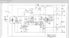
Trying something new to create some fun around here(maybe). I am giving away a FREE Soundcraftsmen tee-shirt to the first person that can tell me what two components determine the A5002 amp's 3 second(approx) turn-on delay and protection reset. And give a description of how it works. This is one of the trickier parts of the design and only the Soundcraftsmen purists and experienced techs will catch it. Good luck!

This screenshot is the best I can do for a schematic since the original file is too big to post here.

I will get the winner's shipping info in a private message.

Ends one week from posting date, and I will post the answer if no one else does by then.
 

Attachments

  • Screenshot from 2020-07-25 11:36:55.png
    Screenshot from 2020-07-25 11:36:55.png
    303.7 KB · Views: 21
Register to hide this ad
It is in the function of the scr and the triac and the 3 seconds is about how long it take to charge the caps.
Put in larger caps, longer delay?
 
It is in the function of the scr and the triac and the 3 seconds is about how long it take to charge the caps.
Put in larger caps, longer delay?
Not quite. But the SCR draining the caps does pull the base of Q33 low to apply voltage to pin 6 of the lm3900 and keep the power off until it's done discharging. But ultimately it is not the timing component that determines the reset or turn-on delay.
 
Can't read the screenshot you sent.
Yeah, it's not good. Not much else I can do with the small file sizes. That has really been the most annoying thing about this site since I have been on here. The original size is 1.3MB for that page. Not allowed, too big.
 
Last edited:
OK, the MA5002 schematic prints to an acceptable size. It is the same design with different part numbers. People can use which ever they are comfortable with. Just note which schematic used in the answer.
 

Attachments

Thanks Jim. It is mostly the first paragraph that sets it apart from normal opamps. It is a current input instead of the usual voltage input.
 
Yes I noticed the current driven, but how it works?
Not going to happen for me.
I'm surprised a couple of those other soundcraftsmen guy haven't taken a stab at it.
 
Last edited:
Well I guess you're going to find out tomorrow. lol The power caps charge and discharge almost instantly. That's why it makes the little noise when the triac turns on.
 
lol Only because I said I would end it in a week. Otherwise, it wouldn't be a big deal seeing the lack of interest in it...
 
Another hint: capacitance(F) X resistance(ohm) = time(s)

What you mentioned about the caps charging reminds me of something else. I got modern replacements for the optocoupler that I'm going to try. They are basically the same thing; except it is a 'zero-crossing' design. Meaning, that it only triggers upon the zero voltage crossing of the AC voltage going through it. That way it turns on and ramps up voltage with the supply itself, instead of possibly triggering when it is at or near max voltage, and creating a huge power surge. More of a soft-start approach. It should help the triac to stay healthy.
 
Last edited:
Turns out I will be gone tomorrow. So I'll settle it now

ANSWER: from the second schematic I posted. The lm3900 is a current input op-amp. When the amp is turned on and if no thermal protection is active, the second stage is fed current through a 15M resistor(R73) into the + noninverting input on pin 1. There is a .22uF capacitor(C28) from the output on pin 5 to - inverting input on pin 6. The opamp tries to match the current on the + input through the - feedback loop with the capacitor to pin 6. That means the output voltage has to continually rise to put the same current through a charging cap. It will rise until input current on pin 2 of the next stage goes above the current on pin 3. When it does, the second stage switches positive and sends power to the optocoupler to turn on the triac and to turn off the protect LED. It also sends positive feedback through R77 to latch the previous stage in the on position. If current is put to pin 6 from the over-current circuit or the temp stage before it, then it will go negative and shut the next stage off. This also sends a negative pulse to pin 11, which then triggers the SCR discharge. When the discharge is done, the timing is allowed to start over again. C28 also acts as a low pass filter for the previous stage. Dual purpose in this case.

So, the two timing components are R73 and C28.
15,000,000 ohm X .00000022F = 3.3 seconds
 
Last edited:
See, I was exactly right, your just better at putting it into word than me. My last post pretty much explained it, no?
T shirt please, and thanks! I love to win.
 
Last edited:
See, I was exactly right, your just better at putting it into word than me. My last post pretty much explained it, no?
T shirt please, and thanks! I love to win.
Editing an old post to make it look like you figured it out is dirty business Jim!
 
I checked with the contest governing body on your answer, and time travelers are disqualified from competing.
Sorry, so close on that one bud. :P lol
 
I'm a dirty player!
That's why I'm an operating engineer, I like dirt.
Ok all kidding aside.
Thanks for the electrical riddle. It has move me a bit further in my understandings of how circuits work.
I read the article and then in your explanation the article made Sense.
I wonder why the 2 or 3 other soundcraftsmen helpers on here didn't take a stab at it? Avionics, goat73, I know there around?
Pride maybe?
As I get to know you I see how your brain reads electrical flow, it's pretty fascinating for me.
Next time you should try one at my level, like what does a diode do. Or how does a light bulb work, lol.
I guess I can just find an old used soundcraftsmen t-shirt at a rummage sale or on eBay.:(
 
Back
Top Bottom