


krjohnson29
New Member
HI!
I don't know if I've posted here before (my account was apparently already created but I can't see that I've posted anything), but I have a little DIY crossover upgrade project I'm working on and was hoping to get some advice.
6 months or a year back or so I bought some Neumi BS5 bookshelf speakers, did the GR Research crossover upgrade on them, and was totally amazed by the results. I thought they were alright before the upgrade, but they were fantastic after! So fast forward to today, I got some Neumi Silk 4 speakers to use as my surround speakers (would have gotten two more of the BS5s, but alas they will not fit in the space allotted by the love of my life). Listened to them, they seem alright, but far less detailed than my front speakers after the upgrade.
So, my thought is that I want to try upgrading the crossover on these too. (More for fun than anything else, since they are just surround speakers.) The crossover seems like an OK design, I don't think I need it to be re-designed, but I'd like to upgrade the part quality. So I traced out the circuit and read the values off of the components that I could find. Some I was a little confused about (hence a couple of my questions) but based on what I had, I drew out a crossover in two pieces which will fit in the box - one on the bottom, one on the back panel.
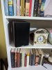 - Speaker Picture
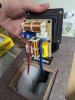 - Crossover Picture
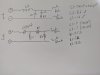 - Crossover Electrical Schematic
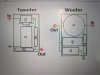 - Upgraded Crossover Layout
But I have some questions that I'm hoping some experienced people here might be able to answer:
1) The yellow poly cap, C1, does not seem to have a label in uF, it only says "565J". Does this mean "5.65 uF"?
2) I'll try to measure the inductors to be sure (don't want to sacrifice them just yet), but for now using a calculator based on the advertised crossover point of 1.65 kHz and the values of the rest of the components, it seems like they should be 1.14 mH and 1.65 mH. This seems huge to me! Does it seem at all correct to you?
3) To get air core inductors that match the 1.14 mH and 1.65 mH values AND fit in the box, I need to get something like 18 gauge wire. But that likely bumps up the DCR of the original iron core inductors by ~0.3-0.5 ohms. Is this something to worry about? Can/should I adjust the values of the resistors in the circuit to compensate?
Thanks for your help!
I don't know if I've posted here before (my account was apparently already created but I can't see that I've posted anything), but I have a little DIY crossover upgrade project I'm working on and was hoping to get some advice.
6 months or a year back or so I bought some Neumi BS5 bookshelf speakers, did the GR Research crossover upgrade on them, and was totally amazed by the results. I thought they were alright before the upgrade, but they were fantastic after! So fast forward to today, I got some Neumi Silk 4 speakers to use as my surround speakers (would have gotten two more of the BS5s, but alas they will not fit in the space allotted by the love of my life). Listened to them, they seem alright, but far less detailed than my front speakers after the upgrade.
So, my thought is that I want to try upgrading the crossover on these too. (More for fun than anything else, since they are just surround speakers.) The crossover seems like an OK design, I don't think I need it to be re-designed, but I'd like to upgrade the part quality. So I traced out the circuit and read the values off of the components that I could find. Some I was a little confused about (hence a couple of my questions) but based on what I had, I drew out a crossover in two pieces which will fit in the box - one on the bottom, one on the back panel.
- Speaker Picture - Crossover Picture - Crossover Electrical Schematic - Upgraded Crossover Layout But I have some questions that I'm hoping some experienced people here might be able to answer:
1) The yellow poly cap, C1, does not seem to have a label in uF, it only says "565J". Does this mean "5.65 uF"?
2) I'll try to measure the inductors to be sure (don't want to sacrifice them just yet), but for now using a calculator based on the advertised crossover point of 1.65 kHz and the values of the rest of the components, it seems like they should be 1.14 mH and 1.65 mH. This seems huge to me! Does it seem at all correct to you?
3) To get air core inductors that match the 1.14 mH and 1.65 mH values AND fit in the box, I need to get something like 18 gauge wire. But that likely bumps up the DCR of the original iron core inductors by ~0.3-0.5 ohms. Is this something to worry about? Can/should I adjust the values of the resistors in the circuit to compensate?
Thanks for your help!

