• The move to the new server is done. There are some software and database maintenance updates in process. This has us passing the hat around to help out. We appreciate any donations. Seriously, even a dollar helps. The payment page may be found here - https://www.audiokarma.org/support.html

SPEC2 stays in protection after restoration

Hello,

I decided to restore my Spec2 after reading some threads about it from users @mattsd and @markthefixer. I replaced all transistors and film capacitors in the power amp boards, power supply board and amp meter board with the exception of the output transistors. I also replaced 2 relays in the power supply board, 1 relay in the meter board and the reed relay RL1 that often goes bad.
I was hoping for help from the pioneer experts in the forum to find where the issue resides. I made some measurements that @markthefixer asked for a member on a similar issue from an old thread as a baseline


Left channel:

vr1 to zero ohms.


pin 22 gr 88.7v

pin 23 gr 1.83mv

pin 14 gr 1.8mv

pin 15 gr -89.9v


across r9 4.7k 2w yellow violet red 53.4v

d2 cathode gr 35.08v

across r4 15k ohm brown green orange 34.4v

across r7 33k ohm orange orange orange 61.7v

across r8 15k ohm brown green orange 27.95v

across r5 1.8k brown gray red 2.12v

across r6 1.8k brown gray red 2.0v


across r11 100 ohm brown black brown -30.8mv

across r12 100 ohm brown black brown -31.8mv


across r13 100 ohm brown black brown -35.5mv

across r14 100 ohm brown black brown -35.2mv


q5 collector gr -26mv

q7 collector gr 1.78mv


Coil to pin 4 to gr 27.6v

Contact to pin 15 to gr -90v


Right Channel:


vr1 to zero ohms.


pin 22 gr 88.6v

pin 23 gr 1.86mv

pin 14 gr 1.83mv

pin 15 gr -89.8v


across r9 4.7k 2w yellow violet red 53.6v

d2 cathode gr 35.13v

across r4 15k ohm brown green orange 34.4v

across r7 33k ohm orange orange orange 62.2v

across r8 15k ohm brown green orange 27.7v

across r5 1.8k brown gray red -2.12v

across r6 1.8k brown gray red -2.03v


across r11 100 ohm brown black brown -30.6mv

across r12 100 ohm brown black brown -30.8mv


across r13 100 ohm brown black brown -0.025mv

across r14 100 ohm brown black brown -.06mv


q5 collector gr -0.895mv

q7 collector gr 1.8mv


Reed relay

Coil to pin 4 to gr 28.7v

Contact to pin 15 to gr -86.2v


Any help I receive will be greatly appreciated.

Regards,
Pedro
 
Register to hide this ad
I'm thinking the DBT stays dim.(?)
How about the amps DC Balance on pin 20, (Use the chassis as the common). What about the idles? Can they be adjusted?
 
When I turn it on while using the DBT with a 100watt bulb, the light turns on bright and as it dims down until it is off, the protection light starts to get brighter until is fully on.

pin 20 to gr 1.88 mv in right, 1.83mv in left

The idles can't be adjusted and give a reading of 0.0mv on both
 
SPEC2 stays in protection after restoration
are you saying it worked before you started ? if so check your work .
 
Before I worked on it it kept going in an out of protection mode. I did double check my work, but I couldn’t find a mistake.
 
See if you can adjust the balance to zero.
Can we see an image of the reed relay(s) you replaced? One image would be good. It might save some time.
You don’t happen to live in Las Vegas?
 
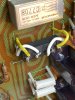
Not sure what you mean to adjust the balance to zero. I am attaching a picture of the relay I used, you can see I connected pin 1 in the relay to the lead that goes to pin 15, is it OK? Does it matter what direction it is installed? I live in NY state.
 

Attachments

  • AFF0CDDA-150D-4308-B0A9-8C8678A49704.jpeg
    AFF0CDDA-150D-4308-B0A9-8C8678A49704.jpeg
    134.3 KB · Views: 51
edit: zeb probably forgot that the spec-2 does not have a dc offset adjust. Plus the pin 20 readings are less than 3 millivolts referenced to ground.

Something for the OP to contemplate: it is probably a mistake repeated in both channels.

Your post DOES give me plenty to work with, ending with q5 and q7 collectors having inadequate voltages to drive idle current.

The ONE thing that does stick out at this point, is the VR2 & VR3 power limiter trimpots, and their initial settings. Are they new?
They MIGHT be operating, due to a too low setting. The manual is uninformative as to an initial setting.
I suspect that the closer the resistance tap is to the thermistor connection - the less sensitive the circuit is.
Which is what you want right now - in lieu of pulling those 4 transistors to completely eliminate their effect. Their effect COULD be felt as far "upstream" as the Q5 & Q7 collectors.

forgive me my brevity tonight - i am working through a pounding headache. (again)
 
I did replace all the trim pots, I forgot to mention this. I left VR2 and VR3 to the lowest setting in the counterclockwise position, since I did not see any information in the service manual regarding that.
 
You could place them in the center and retry. I have a thread that discusses the trim limiters. They don’t work like you think. One goes CW and the other goes CCW to deactivate the circuit. And again I don’t remember what does what.
Yea I forgot about the balance. I should of took more time on a reply.
 
The power limiter trimpots are wired OPPOSITE of each other, so one of them will randomly be full on, while the other will be full off.

Here is the quickest way to "get them out of the way".

Measure the voltage between the bases of Q12 and Q13, connecting the DMM red lead to Q12 base, and the DMM black lead to Q13 base,
randomly choose one of the trimpots, either VR2 or VR3, and start turning it.
IF the measured voltage starts to drop, stop and return the trimpot to it's full setting at that original extreme. THEN go to the OTHER trimpot and repeat.
IF the measured voltage starts to rise - you are on the correct path, turn the trimpot to it's extreme.

I believe that +1.2v at Q12 base and -1.2v at Q13 base will read as +2.4v on the meter - WHEN it is able to control it's idle current, since you can't - I expect it to be lower,

IF the power limiter is operating full on, and it looks like it is, it will reduce the base voltages - apparently to a value far below where idle current can flow.
Thus if a trimpot lowers the base drive, it is going further into current limiting operation.


NOW, if all of the above is horrendously wrong, use the DMM to identify the direction to turn each trimpot to minimize the resistance between the pot TAP and the pin 20 power amplifier output.

If THIS does not bring back the ability to adjust idle current, PULL Q8, Q9, Q10 & Q11 temporarily off the board, and get back to me, measuring and posting the Q12 to Q13 base voltage.
 
Last edited:
right channel

between bases of Q12 and Q13 fluctuates between -0.99v and -1.0v, no changes seen when adjusting either VR2 or VR3 (hard to see since it keeps changing)


left channel

between bases of Q12 and Q13 fluctuates between -01.068v and -1.0072v, no changes seen when adjusting either VR2 or VR3 (hard to see since it keeps changing)


I did used the DMM to measure between the TAP and pin 20 and adjusted al trimpots to where the least resistance was reading. I then measured these again:

Right channel

q5 collector gr 2.0mv

q7 collector gr 1.85mv

Left channell

q5 collector gr -12.5mv

q7 collector gr 1.78mv

I am still unable to adjust idle current, DMM reads 00.01mv on both channel no changes when adjusting VR1

When you asked this:
If THIS does not bring back the ability to adjust idle current, PULL Q8, Q9, Q10 & Q11 temporarily off the board, and get back to me, measuring and posting the Q12 to Q13 base voltage.

Do you mean removing them, powering up without them and measure again the Q12 to Q13 base voltage?

I won't be able to remove Q8, Q9, Q10 & Q11 until Wednesday night, I will do then what you suggest.
 
Somehow, something I either posted or was preparing to post has gotten lost - probably by my fault.
I like that the ground based voltage measurements are identified.

in answer to the question: YES.

Q5 and Q7 collector voltages are key here, they however are to be measured as a differential, one reading: red dmm to q7 collector and black dmm to q5 collector.
as of the time of the measurment of these these readings they are not large enough to turn on the output transistors enough for idle current to flow.

With the power limiters removed, I am hoping to see about 2.4v between Q5 collector and Q7 collector,
+1.2v on the base of Q12, and +0.6v on the bases of the NPN output transistors
AND
-1.2v on the base of Q13, and -0.6v on the bases of the PNP output transistors

The 1.2v and 0.6v + and - use the OUTPUT pin 20 as their (black) DMM reference.
 
I removed Q8, Q9, Q10 & Q11 and then took the following measurements:


Right channel:


between Q5 collector and Q7 collector: -0.99v


Base of Q12: 0.010mv


Bases of NPN output transistors: 0.033mv


Base of Q13: -2.5mv


Bases of PNP output transistors: 0.019mv


Left channel:


between Q5 collector and Q7 collector: -1.07v


Base of Q12 0.011mv


Bases of NPN output transistors : 0.029mv


Base of Q13: -3.1mv


Bases of PNP output transistors: 0.016mv
 
Are you SURE that RL1 contacts are closing?

measuring from Q5 collector TO Q7 collector should show about 2.4 volts.

WHAT is the status of D4, the STV-3H? The STV-4h (d11) is in there as a safety, to limit the open circuit voltage between those measurement points.
 
Can I check if the RL1 contacts are closing while being on the board or do I need to remove them to apply 24v between the coil leads to measure resistance between the contacts? How can I check that D4 and D11 are OK?

If I measure voltage referenced to ground at the RL1 pins this is what I see:

right channel:

to both coil pins 28.6v
to contact that goes to pin 15 -89.9v
to contact opposite contact pin -76v

left channel:

to coil pin to pin 4 28.2v
to opposite coil pin 28.8v
to contact that goes to pin 15 -90.04v
to contact opposite contact pin -76.2

Something that I have a question is if the relay needs to be installed in a certain orientation. Right now the relay pin marked with the notch as pin 1 is connected to the lead that goes to pin 15
 
Last edited:
What is the exact parts number of RL1? Those measurements don't make sense. Especially that 14 volt drop. (-90.04 TO -76.2)

Hamlin # (from mouser) 934-HE3621A2400 ?

pin 1 one half, form A contact

pin 2 positive side of relay coil
pin 3 negative side of relay coil

pin 4 other half, form A contact

LOOK at mattsd's thread: https://www.audiokarma.org/forums/i...r-spec-2-recap-and-restoration-thread.797294/

something's fishy - so start by reading the part number off of the relay and posting it.

I would expect to see a 28v reading, a 0v reading,
( coil power and coil "ground" of an operating relay coil)
and TWO -90v readings.

Instead of the contacts, you could have it across the coil - which would have about 2600 ohms of DC resistance, and generate the readings I have seen.
 
Last edited:
I am using relay HE3621A2400, I installed based on Matt’s thread picture with pin 1 (contact) on the lead that goes to pin 15 on the board, pin 2 (coil) on the lead that goes to pin 5 on the board, pin 3 (coil) on the lead that goes to pin 4 on the board and pin 4 (contact) on the lead that goes to one side of R13 and R14.

I removed the relays and tested them by applying 24v between the coils and measured resistance between the contacts and got 0 ohms after applying the 24v.

I installed the relays again and measured voltage between ground and all 4 pins of the relay, see below:

right channel:

pin 1. -89.99v
Pin 2. +28.75v
Pin 3. +28.14v
Pin4. -76.02v

left channel:

pin1. -89.90v
Pin2 +28.75v
Pin3. +28.15v
Pin4. -76.19v
 
The relays are not being activated. I will trust that you have correctly identified the pins.

pin 3 of the relay MUST be pulled far closer to ground potential, to activate the relay.

Why there is 13.8 volts across the open contacts remains to be deciphered.
.
AWH-045 pin 5 is a constant 28.2V from the power supply AWR-093 pins 32/33/34 raw unregulated 28v dc. It is reduced by R49 a 22 ohm resistor.
Something Is off with the amp pc board pattern by the relays, because the pin solder pad that should be getting the +28v shows up in the manual as a DISCONNECTED pad - your measurement
of 28v on relay pin 2 says SOMETHING was done to connect it. Perhaps a picture of the BACK of the board will shed some light on what was done

AWH-045 pin 4 is pulled down much closer to ground to activate the relay coil.
It is pulled down by either pin 18 or pin 19 of the meter amplifier board AWM-081.
That is done by Q13's collector, a 2sc945 and it is in the tail end of the protect circuitry where lots can go wrong.

That pin 18 or pin 19 voltage controls Q15 a 2sc1384 that drives the protection lamp

While you can QUICKLY AND BRIEFLY test the power amp idle current by grounding AWH-045 pin 4
do not "force it" for long.

That will allow the re-installation of the 4 power limiter transistors I had you remove as a test.

so:
1. ground the AWH-045 pin 4
2. measure the presence of idle current - turn up A BIT, THEN TURN IT BACK DOWN
3. replace the 4 removed transistors.
4. RE-test the idle current.

Then we will start to address the issues of the spec-2 NOT pullng in RL1.


One thing you can do is to re-evaluate the pinouts of the transistors you used.
Some of the transistors MAY be "C" versions - such as "ksc945c", with a trailing C
That means the ksc945 is ebc, while the ksc945c is ecb.

THAT C version pinout change crap has tripped up TOO MANY noobs, and is the MAIN reason that I have weeded them OUT of MY lists.Invariably someone gets tripped up by them and it costs a lot of time to figure it out.
 
Last edited:
Back
Top Bottom