
• The move to the new server is done. There are some software and database maintenance updates in process. This has us passing the hat around to help out. We appreciate any donations. Seriously, even a dollar helps. The payment page may be found here - https://www.audiokarma.org/support.html

SPEC2 stays in protection after restoration

Mark,

I connected pin 4 to ground one channel at a time and I was able to adjust idle current without the 4 removed transistors.
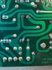
I will do it again after I reinstall the transistors. I am also attaching pictures of the back of the boards showing the area where the relay, R49 and pin 5 are.
Looking at your last paragraph makes me wonder if I made that dumb mistake. I ordered KSC945CYTA the actual transistor case has this marking C945 at the top and YCF33 at the bottom. I installed them following EBC pin out. Are these transistors actually ECB?
 

Attachments

  • 0E12C8FB-2665-46E4-972B-92A5E73D3824.jpeg
    0E12C8FB-2665-46E4-972B-92A5E73D3824.jpeg
    150 KB · Views: 11
  • 38AC2666-0A71-441C-8E50-52527702BBB6.jpeg
    38AC2666-0A71-441C-8E50-52527702BBB6.jpeg
    131.7 KB · Views: 11
Mark,
. I ordered KSC945CYTA the actual transistor case has this marking C945 at the top and YCF33 at the bottom. I installed them following EBC pin out. Are these transistors actually ECB?

YES - the pinout for what you purchased (KSC945CYTA) from mouser IS ECB....

AND you should also note that the power limiter transistors that you "test removed" ARE ALL ECB type ksa733c and ksc945c. So ALL FOUR transistors were installed incorrectly. I WOULD replace them with four NEW transistors and not trust to luck that the originals were not damaged - in an area where they could EASILY been damaged.


this is a PRIME example of WHY I stopped recommending the KSA733 and KSC945 transistors.
The sheet even says that the c945 and c945c variants have the SAME top marking.
 
Last edited:
Thanks Mark for all your time and help. I do have spares and I will install them correctly and report back to you probably in a week. If I am not mistaken the meter board has one of KSC945c installed at Q13, and one of the KSA733c installed at Q11, so I will have to replace those and install correctly.
Would you mind giving me the transistor replacements you recommend in lieu of KSA733 and KSC945?
 
Last edited:
Mark, thanks for the information, I will order some of those.
I found some time today and went ahead and installed 10 new transistors 8 on the power amp boards and 2 at the meter board. I powered the amp up and the protection circuit kicks in for about 5 to 8 seconds and then it turns off.
I am able to adjust idle current in the left channel, however on the right channel I still can’t adjust it.
 
protection looks like it is operating properly.


remeasure the Q5 collector (red dmm) to Q7 collector (black dmm) voltages for both channels.
Then
remeasure the q12 base (red dmm) to q13 base (black dmm) voltage also for both channels.
 
Left channel
Q5 to Q7 -2.22v
Q12 to Q13 2.21v

Right channel
Q5 to Q7 fluctuates between -4.2mv to -4.6mv
Q12 to Q13 fluctuates between -1.063v and -1.08v
 
left and right channels:
ground referenced voltages found on each side of R7 33k ohms (orange orange orange gold)
ground referenced voltages found on each side of R9 4.7k 2 watts.
This will report both external as well as internal power supply voltages.

please post the actual transistor substitutes used in the channels, from Q1 through Q13 inclusive.

please double check the ground referenced voltage found at the junction of R13, R14 and RL1, both with relay off, and with relay forced on. Both channels. Gotta be SURE the right channel RL1 contacts are closed.
 
Last edited:
Transistors used:

Q1 > KSA992FBU (2)
Q2 > KSA992FBU
Q3 > KSA992FBU
Q4 > MJE15032G
Q5 > MJE15032G
Q6 > MJE15032G
Q7 > MJE15033G
Q8 > KSA733CYTA
Q9 > KSC945CYTA
Q10 > KSC945CYTA
Q11 > KSA733CYTA
Q12 > MJE15032G
Q13 > MJE15033G
Q20 > KSC2383YTA

Right channel:

ground referenced voltages found on each side of R7 33k ohms (orange orange orange gold) = -93.3v and -28.9v
ground referenced voltages found on each side of R9 4.7k 2 watts. = 35.3v and 93.01v
ground referenced voltage found at the junction of R13, R14 and RL1:
with relay off = -79.1v
with relay forced on = -79.1v

Left channel:

ground referenced voltages found on each side of R7 33k ohms (orange orange orange gold) = -93.05v and -28.64
ground referenced voltages found on each side of R9 4.7k 2 watts = 35.52v and 92.81v
ground referenced voltage found at the junction of R13, R14 and RL1:
with relay off = -78v
with relay forced on = -92.401v

I measured the ground referenced voltage at junction of R13, R14 and RL1 as soon as I powered it on (not sure if this is what you meant by 'with the relay off') and then as the protection light turned off.
 
The data is obvious, the duff right channel is not connecting to -90v rail when the relay is supposed to be forced on.

Now - I can't tell if the RL1 isn't getting coil current, or there is an interruption in the circuits connecting the contacts into the pc board pattern.

right channel board:
powered OFF:
ohmmeter test for continuity from the junction of R13, R14 TO the relay's final flying lead soldered to the pins "dead bug style", the OUTER contact closer to pins 4 through 8.
Hit the relay's lead, not the solder blob nor the flying wire.
ohmmeter test for continuity from pin 15 TO the relay's final flying lead soldered to the pins "dead bug style" - the INNER contact closer to the center of the board.
Hit the relay's lead, not the solder blob nor the flying wire.


powered on, but NOT forced.
confirm presence of +28v on BOTH sides of R49 (22 ohms)
confirm presence of +24 to 28v at relay coil solder connection Hit the relay's lead, not the solder blob nor the flying wire.
confirm presence of +24 to +28v at OTHER relay coil solder connection and relay not being "forced". Hit the relay's lead, not the solder blob nor the flying wire.
ground pin 4 of the board THROUGH the DMM wired up as a current meter and read the coil current, basically "forcing it". (the DMM set on current, the probes moved to the appropriate meter jacks - it will "look" like a wire to the circuit, yet to YOU it will report the value of the current flowing through it.
 
Continuity checked OK for both contact relay leads.

ground to both sides of R49 not forced = 28.2v for both sides.

ground to both coil leads not forced = 28.2v

Current from pin 4 to closest relay lead = 0mA
Current from pin 4 to second relay lead = 0mA
 
edit start
Close reading of posts leaves some doubt in my mind.
1. "forcing" the relay on, is connecting a bare metal chassis ground to pin 4 of the AWM-081 amplifier board.
temporarily forcing the relay on can also be accomplished by setting up the DMM to measure current, connecting one of the DMM leads to a bare metal chassis ground and the other DMM lead to pin 4.

this phrase:
Current from pin 4 to closest relay lead = 0mA
Current from pin 4 to second relay lead = 0mA
read literally causes me doubt.
pin 4 in itself is not a force point, the connection of pin 4 to a bare metal chassis ground IS forcing it.
Reading current to a pin 4 that is not grounded (or doesn't have a protect circuit grounding it) WILL show 0mA. Because the relay isn't being forced.

I should have added another step to testing, where I asked you to "confirm presence" to read like this:

confirm presence of +28v on BOTH sides of R49 (22 ohms)
confirm presence of +24 to 28v at relay coil solder connection Hit the relay's lead, not the solder blob nor the flying wire.
confirm presence of +24 to +28v at OTHER relay coil solder connection and relay not being "forced". Hit the relay's lead, not the solder blob nor the flying wire.
confirm presence of +24 to 28v at pin 4 of the AWM-081 amplifier board.
ground pin 4 of the board THROUGH the DMM wired up as a current meter and read the coil current, basically "forcing it". (the DMM set on current, the probes moved to the appropriate meter jacks - it will "look" like a wire to the circuit, yet to YOU it will report the value of the current flowing through it.

Please rerun the test WITH the extra step. And please tell me how you did the process of forcing the relay to operate in the previous posts.

edit end

Power off.

Measure ohms between two coil leads (two closest to center, outer two leads are contacts) .At relay body.
Reverse the ohmmeter leads and take another reading (internal diode)

specified 2150 ohms (+/- 10% is 1935 to 2365), if not in that range of resistance:

Take relay off of board(if glued, just disconnect flying leads), test on bench. Suspect coil is open.

UNUSUAL failure.
 
Last edited:
Mark,

I misunderstood and took measurements wrong. I grounded pin 4 then one lead of the multimeter at pin 4 using the multimeter set to measuring current the other multimeter lead at coil lead that is how I got 0mA.
ground to both sides of R49 not forced = 28.2v for both sides.

ground to both coil leads not forced = 28.2v


I verified there is 28.2v at pin 4.
I connected the multimeter one lead to ground the other one at pin 4 and measured current = 13.2mA
I measured coil resistance = 2.1Kohms same measurement after reversing leads.
 
That means the relay coil is operating. Second half of the problem is being sure the contacts are closed.


If the right channel doesn't have idle current, force it on, the right channel relay should have -90 v on both contact lead pins. And idle current should be adjustable.

IF idle current isn't there and adjustable;
remeasure the Q5 collector (red dmm) to Q7 collector (black dmm) voltages for both channels when forced
Then
remeasure the q12 base (red dmm) to q13 base (black dmm) voltage also for both channels when forced.

is the protect light turning off, and the RL1 on both channels pulling in?
 
When I forced right channel on, I measured -92.2v and -92.15v at both contact leads and I can also adjust idle current on right channel. The protection light turns off after 5 to 8 seconds.

Right channel:
Forced on voltage between Q5 and Q7 = -1.82v
Forced on voltage between Q12 and Q13 = 1.82v

Left channel:
Forced on voltage between Q5 and Q7 = -2.26v
Forced on voltage between Q12 and Q13 = 2.25v
 
Before you started, did you measure the idle current on both channels?

Did you disconnect the D4 STV- 3H diode from the circuit at all?
The D4 STV-3H diode is the thermal diode that controls the idle current.

The D11 STV-4H diode is included as a "safety" to prevent the idle current from going too high should the D4 STV-3H circuit (which includes VR1 470 ohms) open up (say - with a broken wire).

The observed operation of the protection light IS CORRECT.

It stays lit during the timing interval during the power up sequence.

What exactly is the problem now? I think somewhere back there - we fixed it....
 
Mark,
Before I started I was able to measure idle current in both channels.
I didn’t disconnect D4.
After I installed new transistors correctly (I made the mistake of installing them following EBC layout when they were ECB) the protection light works fine.
The problem now is that I am unable to adjust idle current on the right channel at all, it measures zero. I can adjust it when I forced it though.
 
Hmmm, considering it all:
forcing the right channel (grounding pin 4) gets the right channel idle current flowing, but protect light off has NO idle current flowing in the right channel .
Protect light OFF allows left channel idle current to flow.

Prove that the wire from right amp card AWH-045(right) pin 4 to meter board AWM-081 pin 19 is connected and conducting electricity.
The wire from left amp card AWH-045(left) pin 4 to meter board AWM-081 pin 18 is connected and conducting electricity.

Right channel:
Forced on voltage between Q5 and Q7 = -1.82v
Forced on voltage between Q12 and Q13 = 1.82v

Left channel:
Forced on voltage between Q5 and Q7 = -2.26v
Forced on voltage between Q12 and Q13 = 2.25v

Stop forcing on for now.

Finding and fixing a broken wire from AWH-045(right) pin 4 to awm-081 pin 19, so that protect light OFF allows right channel idle current to be adjusted means no more readings are needed.

First provide pin 4 voltage to ground from left channel and pin 4 voltage to ground from right channel when protect light is ON.
Then provide pin 4 voltage to ground from left channel and pin 4 voltage to ground from right channel when protect light is OFF.

Please provide protect light ON measurements of left and right channels, q5 collector to q7 collector, q12 base to q13 base and R13-R14 junction voltage to ground.
Please provide protect light OFF measurements of left and right channels, q5 collector to q7 collector, q12 base to q13 base and R13-R14 junction voltage to ground.
 
Mark,
I want to thank you for your time and expert advise that you have given me during the last few weeks.
Once I saw your last message regarding the connection between pin 4 at the right amp board and pin 19 at the meter board, I checked and found the bad wire I was using as a temporary connection setup in order to be able to take measurements at both boards. Once I replaced that wire, I fired up the amp and I was able to adjust idle current on both channels.
Thanks again for all your help, much appreciated!
 
Back
Top Bottom