• The move to the new server is done. There are some software and database maintenance updates in process. This has us passing the hat around to help out. We appreciate any donations. Seriously, even a dollar helps. The payment page may be found here - https://www.audiokarma.org/support.html

ST-70 on the fritz

ADClosson

Member
I recently had trouble getting my fully restored ST-70 to bias properly. The left channel didn't have enough range to bring the bias within spec. It kept reading high, around 2.5 volts. This issue spontaneously resolved and I enjoyed the amp for a few weeks.

Then today the left channel fizzled out. By that I mean the channel faded then went silent while listening to music.

I changed tubes, hoping that might be the issue, but the biasing issue returned—I can't bring the left channel into spec. Worse still, in rolling various tubes in and out in an attempt to troubleshoot (one rectifier tube seemed to be defective) I introduced a new problem. Randomly, one or two tubes wouldn't glow upon start up. I would rotate and reseat, and sometimes the issue would resolve and other times it would simply move, but not logically, i.e. it would not simply follow the tubes I had moved.

On one such occasion, when I started up the amp and was observing the non-glowing EL-34s, the inactive tubes started shooting blue flame like pulses of light and the entire amp vibrated! I of course quickly unplugged the amp. I then reconfigured the tubes again and started it up. This time all tubes glowed, but within ten seconds the tubes again shot blue flames, including the rectifier.

Clearly, matters have gotten far worse. Any suggestions? At this point, I probably need to find a qualified tech to repair. I'm in Dallas. Anyone have suggestions?

Thanks.
Aaron
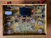
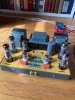
IMG_1065.jpg IMG_1066.jpg
 
Last edited:
Register to hide this ad
If it were me and if he’s still around I’d contact Bob Latino. He sells and supports Dynaco kits and he knows the ST70 inside and out. He can probably send you in the right direction and sell you any parts you’ll need. I had a problem with my ST70 and he was a big help.
 
Could be bad solder joint(s) in spite of what appears a careful neat build.
I do fervently wish the kit suppliers would include screen stoppers and the full rectifier socket mod with every kit BOM.
 
Don’t just start swapping parts until you know what the actual fix is. That can be a slippery slope that can ( but not always) sometimes cause more problems.
 
something else worth doing, ohm check from ground to the two bias test points with the power off. Confirm that you read something near the 15.6 ohm value of the resistor. For a more exact reading, short the test leads out, note the reading, then subtract that from whatever you measure at the test points. If those resistor(s) have gone high in value for some reason the voltage across them will be high but it won't indicate a problem with how much current the tubes are flowing.


the spark show makes me think you had a tube failure. If that happens it can fry the resistor.
 
I see you painted the chassis inside and out and wonder if you thought of making absolutely sure all of the ground connections that rely on clean chassis connections are in fact good and solid? Also I can't tell if the necessary pin 1 to pin 8 jumpers are in place on the EL34 sockets?
They look like they might be joined.
Perhaps run connections from the ground point of the cathode resistors to the common ground point next to the quad cap, and add the screen stoppers and the rectifier socket mods as well. The last two can protect the three transformers and the tubes from catastrophic failures.
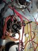
I'll post pics of how I did it on mine.
20210303_090314.jpg20210303_090156.jpg
 
I've run proper pentodes without the suppressor connected to anything. It actually works, probably not as linear as it should be but it didn't seem to cause any particularly nasty effects.

The random "tube won't light" thing does make me wonder about the tube sockets or connections to them. Those sockets don't look old but I don't know how good the modern ceramic sockets are either. Never used them but I've heard mixed things about them.
 
That brown and white wire used for the filaments looks awfully thin. I wonder if there is a short somewhere....
Shorted heater lines would likely produce magic smoke from the heater wiring and PT. More likely a flakey solder joint or two with the new sockets.
 
Last edited:
Thanks, all. I didn't perform the rebuild, but it has run flawlessly for two years until just recently. I scheduled an appointment with a local Dallas tech. Hoping he can sort it out, as it's beyond my capabilities at this point.
 
This sounds like intermittent output tube sockets or a cold solder joint at one or more filament connections. This problem prevented the EL34s from heating, and the unloaded B+ voltage then rose enough to cause arc-over. That, in turn, killed the rectifier. Make sure your tech doesn't use Chinese sockets if he confirms that they need to be replaced. I only use NOS, but from all accounts, Belton is a reliable alternative. My first tech job was in Dallas. It was a shop called "Butler Electronics," right up the street from Hillcrest Hi-Fi and Olson Electronics, across from SMU. :)

Jack
 
Just want to add, this amp has the diode tweak for the 5AR4. Make sure your tech doesn't change it in an effort to make the amp original.

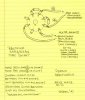
5AR4 Diode Tweak.jpg

Jack
 
I don't see diodes on OP's amp. I think you may be looking at @Pio1980 's amp.
Correct, two 1N4007 in series, in series with the HV PT source legs with their positive ends bridged. This halves the load on each tube diode side by sharing the load between them and negates piv concerns. The tube becomes a parallelled thermal ramping resistor. From a @dcgillespie suggestion, as is the 100 ohm screen suppressor resistors on the screen taps. Change sockets wiring accordingly.
 
Last edited:
I have those same Chinese sockets because I got my amp halfway through a rebuild. They have had some connection problems. I retensioned all of them and no longer swap out tubes.
 
I recommend wetting tube pins with a dip in lighter fluid before insertion to clean contacts and ease insertion.
 
Correct, two 1N4007 in series, in series with the HV PT source legs with their positive ends bridged. This halves the load on each tube diode side by sharing the load between them and negates piv concerns. The tube becomes a parallelled thermal ramping resistor. From a @dcgillespie suggestion, as is the 100 ohm screen suppressor resistors on the screen taps. Change sockets wiring accordingly.
I don't understand this description about bridging and halving the load. The series diodes simply add add their PRV capability to that of the tube, helping to prevent that one type of failure. The sketch I included was posted to another tube audio forum by Eli Duttman many years ago. If I had to guess, neither of these individuals was the first to use it. :)

Jack
 
I don't understand this description about bridging and halving the load. The series diodes simply add add their PRV capability to that of the tube, helping to prevent that one type of failure. The sketch I included was posted to another tube audio forum by Eli Duttman many years ago. If I had to guess, neither of these individuals was the first to use it. :)

Jack
Put a jumper between the tube rectifier plates after the diodes, the load then is thru both sides together rather than shuttling between them one at a time, doubling current capacity.
 
Back
Top Bottom