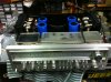
My terminology is skewed. Late at night.
The one-turn pot is zero and the 25-turn is midway.

Sent from my iPhone using Tapatalk
I'm still worried about us not being "on the same page"
so:
recommended parts are multi turn offset
and
single turn idle
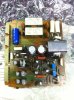
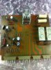
offset is buried near the center of the board
idle is right up at an edge where the transistor cable connectors plug in.
restating it all at once, hopefully unambiguously:
the multi turn 500 ohm trim pot adjusts the amplifier's output voltage, this offset voltage is adjusted to 0.000 volts ,
this multi turn trim pot is buried near the center of the printed circuit board
and this multi turn pot should be at 12 of 25 turns -- centered --
it has THREE separate connections on the foil pattern
and
the single turn 500 ohm trim pot for amplifier internal idle current adjustment
is right up at the edge of the printed circuit board where the transistor cable connectors plug in.
This single turn trim pot should be fully ccw looking at it face on,
giving zero ohms
it has three connections BUT one side and center tap are connected together by the foil pattern,
reading zero ohms from this doubled connection to the remaining connection of the three