• The move to the new server is done. There are some software and database maintenance updates in process. This has us passing the hat around to help out. We appreciate any donations. Seriously, even a dollar helps. The payment page may be found here - https://www.audiokarma.org/support.html

Stereo indicator light flickers occasionally but does not stay on when tuned to a strong station.

MrBill—1

New Member
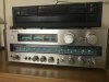
I have a Sony STR-V6.
The stereo indicator light flickers (rarely) but is usually off when tuned to a strong signal.
Is there a way for me to increase the sensitivity so that it illuminates with a weaker signal?
Intuition tells me that there must be a way but I really have no idea at all what the problem may be.
 
Register to hide this ad
The light indicates how well the signal is being pulled in, if it stays bright and steady you have a strong constant signal. So, you need an antenna of some kind. You could use anything from a length of speaker wire which you move around until the stereo light stays bright or you could use a longer wire that goes outside. Then of course you could spend the bucks on an aftermarket antenna.
 
Thanks.
I have an antenna rigged but it IS just speaker wire.
I have been thinking of dropping my cable subscription and getting an antenna to receive over the air digital TV broadcast. Do you think there is a way for me to use such an antenna for radio reception also?
 
The stereo indicator light flickers (rarely) but is usually off when tuned to a strong signal.

Tell us what you mean by strong signal. Do you mean a signal that is strong as indicated by the meter or are you just referring to a known local station?

What does the signal meter indicate for a strong signal? You problem may be signal strength related, but we need to know what you consider a strong signal. If the signal strength meter is indicating a strong signal, the you issue you have may not be signal strength related.

On this receiver the FM stereo indicator light is not a direct indication of signal strength. This is the purpose of the signal strength meter.

All things being equal it will light on a weaker station although the reception may be noisy. There is a point when the signal is weak enough the FM stereo light will not light.
 
Last edited:
There is a home fix for this. Did you get your can of residue free contact cleaner? If so, you are in business. Locate the tuning gang. On the tuning gang will be a trimmer called OSC or oscillator. Spray the trimmer and work the trimmer back and forth returning it to the original position. This should cure no stereo condition and weak reception. Also, use this trimmer to adjust station to dial pointer. This home fix has worked for me many times and I am betting it will for you.
 
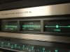
I LIKE MUSIC, there are 3 meters on my receiver. The left one is left power only.
The center meter is dual use. It displays right channel power and, by pushing a button on the right side of the face of the receiver, it displays signal strength.
The right meter shows when you have tuned to the center point of the station. The signal strength scale is from 0-5. The signal strength in the photo is about 3.5. I would think this would be strong enough to make the “stereo” light come on and stay on.
I have attached photos to clarify.
A4FEBF35-BB53-4A68-8116-771499DB4596.jpeg57B1F747-46C1-42B9-BBB7-52C7F6078C99.jpeg
 
For those following the theory of operation of an FM receiver, the local oscillator, if adjusted correctly is not directly involved with signal strength or detection of the 19 kHz pilot signal (signal that turns on the FM stereo indicator).

The OP stated that the FM stereo light is out when receiving a strong signal. Before we start having him do things, we need to know what he means by strong signal.

The stereo indicator light flickers (rarely) but is usually off when tuned to a strong signal.

If the OP really meant that the FM stereo light is off when tuned to a weaker signal, (not a strong signal as he posted), that is a different story.

A quick adjustment of the RF front end per the service manual using an off the air station and the receivers signal strength meter may help.

I just noticed your post with the pictures.
In general the indication of signal strength as shown in your pictures should be enough to cause the FM stereo light to come on.

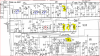
Trouble shooting from a distance is not an exact science, but it would appear that your issue is not entirely signal strength related. Just going by the info at hand I would try adjusting RT205. This is the adjustment for the 19 Khz pilot signal that is used for FM stereo reception including the operation of the FM stereo indicator light.

Note the position of RT205, tune in your strong stereo station and turn RT 205 one direction or the other and watch the stereo indicator light. If this causes the FM stereo light to come on, set RT205 in the center of the range where the stereo light comes on.


upload_2017-12-14_16-1-37.png
 
I LIKE MUSIC,
Thanks so much.
I agree that my description of the problem was awkward.
I was asking if there was an adjustment that could be made to make the lamp light with a weaker signal reasoning that it would certainly come on with a stronger one. Expanding the scale or lessening the selectivity of the circuit.
I am unfamiliar with the nomenclature.
I am a noob.
I believe you understand my meaning.
I don’t know why this kind of thing would ever need to be adjusted but suspected there would be a way to do it.
I’ll do this first and let you know.
 
There is a home fix for this. Did you get your can of residue free contact cleaner? If so, you are in business. Locate the tuning gang. On the tuning gang will be a trimmer called OSC or oscillator. Spray the trimmer and work the trimmer back and forth returning it to the original position. This should cure no stereo condition and weak reception. Also, use this trimmer to adjust station to dial pointer. This home fix has worked for me many times and I am betting it will for you.


There is a known condition with these STR-V5/6/7, most of the time the stereo light will not come on at all. The fix is indeed cleaning and moving one of the trim pots on the board by the tuning gang, probably the one mentioned above. Alas I only found out after I sold my lovely V5 because it could not receive in stereo!

Also worth having a look in the tuner forum, there is a sticky thread on analog tuner cleaning. Once you are inside it will only take a couple of minutes and has made big differences on several of my tuners.

Let us know how it works out.
 
Even though the light doesn’t come on the old Sony DOES receive and play in stereo.
Thanks Raynald.
Will let y’all know.
 
Even though the light doesn’t come on the old Sony DOES receive and play in stereo.
Thanks Raynald.
Will let y’all know.

Now that is new and different information. It changes what one might want to look for.

When asking for help it is not a bad idea to include all relevant information.

If the received FM signal is in stereo, verified by listening, then things change.

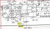
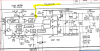
Look at the voltage at pin 9 of IC202. If the voltage is good there (the two voltages are stereo and non stereo). You should see the voltage change when you tune in a stereo FM signal. If it does, then it will be a matter of tracing the circuit back to the stereo indicator and looking for bad connections and so on.

upload_2017-12-14_16-51-58.png
 
As I said. Newby here.
I am a technician myself but have no experience with these things.
It is, of course, necessary to include all relevant information.
Just beginning the hobby. It didn’t occur to me that the receiver may or may not be playing in stereo.
The power meters show different activity on each channel and different “sounds” can be heard coming each.
I really appreciate all the help and need all that I can get.
 
There is a known condition with these STR-V5/6/7, most of the time the stereo light will not come on at all. The fix is indeed cleaning and moving one of the trim pots on the board by the tuning gang, probably the one mentioned above. Alas I only found out after I sold my lovely V5 because it could not receive in stereo!

Also worth having a look in the tuner forum, there is a sticky thread on analog tuner cleaning. Once you are inside it will only take a couple of minutes and has made big differences on several of my tuners.

Let us know how it works out.

Raynald, oscillator trimmer cleaning works at least 3 out of 4 times on all the BOTL and MOTL receivers that have come through the door. IME, most vintage receivers suffer from no stereo so this has been a lifesaver and a moneymaker. I just did the deed on a TOTL unit recently and got a good result. BTW, sometimes the oscillator trimmer is not labeled. It is usually at the end and by itself.
 
For those following the theory of operation of an FM receiver, the local oscillator, if adjusted correctly is not directly involved with signal strength or detection of the 19 kHz pilot signal (signal that turns on the FM stereo indicator).

The OP stated that the FM stereo light is out when receiving a strong signal. Before we start having him do things, we need to know what he means by strong signal.


If the OP really meant that the FM stereo light is off when tuned to a weaker signal, (not a strong signal as he posted), that is a different story.

A quick adjustment of the RF front end per the service manual using an off the air station and the receivers signal strength meter may help.

I just noticed your post with the pictures.
In general the indication of signal strength as shown in your pictures should be enough to cause the FM stereo light to come on.

Trouble shooting from a distance is not an exact science, but it would appear that your issue is not entirely signal strength related. Just going by the info at hand I would try adjusting RT205. This is the adjustment for the 19 Khz pilot signal that is used for FM stereo reception including the operation of the FM stereo indicator light.

Note the position of RT205, tune in your strong stereo station and turn RT 205 one direction or the other and watch the stereo indicator light. If this causes the FM stereo light to come on, set RT205 in the center of the range where the stereo light comes on.


View attachment 1065997

I am not a tech so I defer to your expertise. However, my practical experience and success rate say otherwise. This being said, seeing a tuner tech is always a good idea. I would never recommend against that. However, when flipping receivers that are worth less than $100, there is no money for a tuner tech visit. Cleaning the osc trimmer works.
 
OK
I have a picture and a video to share. I have circled in RED the trimmers that I sprayed with the CRC cleaner and worked with a screwdriver for a couple of minutes. I took care to position them as they were before I started.

Trimmers.jpg

I would attach a video but, for now, I don't know how. There really doesn't seem to be much of a change in the stereo light performance at this point.
Of these trimmers, which one do you think may most likely to the the oscillator trimmer?
As I Love Music suggested, I am about to check voltage pin 9 of IC202,
 
This is what I was trying to avoid. Random suggestions that are wrong, without the correct follow up information and instructions.

The devices that you have circled are not trimmers... as referenced in this thread.

They are variable inductors and do not benefit from spraying of cleaner.

Do not use a metallic tool such as a screwdriver on these. The core material (what you moved) is fragile and easily broken.

There are special RF alignment tools for this purpose.

The first, next thing to do is to check the voltage at pin 9 of IC 202. Monitor this voltage as you tune in a station, that is go from not having a station tuned in to having a strong stereo station tuned in. This should have been done prior to doing anything else.

Hopefully the CRC cleaner that you used is non-residual at RF frequencies, and this is not the same as what might work for the typical volume or tone control or switch contact.

It is likely that the oscillator trimmer capacitor is, although it is difficult to see, is one of the two that I marked. It works in conjunction with a variable adjustable inductor to allow the dial pointer to track accurately. upload_2017-12-15_19-39-22.png


Okay, here we go.,.

upload_2017-12-15_19-55-24.png

The devices that I have marked in yellow are the adjustable inductors referenced above. They do not need to be cleaned.

The parts that I have circled in blue are the trimmer capacitors. they are located on the side of the main tuning capacitor. Again it is difficult for me to tell from your picture.

The trimmer capacitor that I have circled in red is the local oscillator trimmer capacitor as referenced in previous posts.

Here is the location per the service manual for the inductors that you moved. The four together on the main tuner board and the separate on (my yellow mark) that is on the RF front end board.
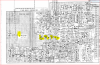
upload_2017-12-15_20-16-6.png

Again, the next, first, best thing to do is the monitor the voltage at pin 9 of IC 202 as described above. This gives us a starting point.

I am a technician myself

I mean no disrespect. Tell me your level of technical ability. I took it at face value that you would know the difference between an inductor and a trimmer capacitor. Again, no disrespect, but this will help me structure my responses.

Let us know the result of the IC202 pin 9 test. Be careful not to let you test probe slip and cause a short to adjacent pins, the chassis or some other part.

 
I do not feel disrespected at all. I do indeed appreciate your comments.
As I have said, I have no experience with electronics. You of course know that medical doctors and meteorologist are also technicians but they are not likely to be familiar with electronics either.
I am a finishing process engineer. I review and suggest process changes in manufacturing and finishing systems (painting operations) to increase output and reduce the incidence of defects.
Anything involved in a metal finishing operation from stamping to final paint and inspection. Typical customer base is automotive but some are appliance, casket, plastics injection molders (gas pumps) and so on.
There does not seem to be any damage done at this point, at least it isn't apparent to me yet.
I will let you know asap.
I have a volt/ ohm meter. As long as I am thinking about it, what kind of oscilloscope might be appropriate for a hobbyist? I was just looking at Craigslist a little bit for one.
 
There are a lot of options for a used oscilloscope.

The 2xxx Tektronix are popular here as are the 465 and up models.

An oscilloscope with a 20 MHz bandwidth or more is okay for audio work, but it you might stumble :eek::D into a unit with issues in the FM section (would that ever be likely to happen...) an oscilloscope with 100 MHz bandwidth would be useful and not a lot more money. Good quality probes with the correct bandwidth are not a bad idea along with them having selectable attenuation (1 to 1/1 to 10).

If you are looking at a used oscilloscope, check all of the functions, check all of the switches and controls for smooth and noise free operation as seen on the screen. Check the traces for clean bright display and good focus even at high sweep rates. While it is not needed, I like to have on screen numeric display of what the oscilloscope is displaying.

Dual trace is very handy to allow you to compare wave forms or look at both the right and left channels at the same time.

Check pin 9 of IC 202 as previously detailed and let us know. And when determining if the receiver is going into the FM stereo mode, check by switching the stereo/mono function switch on the front of the unit and listen for a difference and look for a difference on the power meters.
 
Back
Top Bottom