

You are using an out of date browser. It may not display this or other websites correctly.
You should upgrade or use an alternative browser.
You should upgrade or use an alternative browser.
Stereo indicator light flickers occasionally but does not stay on when tuned to a strong station.


MrBill—1
New Member
I adjusted RT205 to the far right, then the far left. The light did not come on so I readjusted it back to center (where it was).
Grounded my meter and touched pin 9. The light came on! Voltage reading was .8.
I stepped back and listened closely. There was a difference in sound.
I flipped the mode switch from stereo to mono, the stereo lamp went off. I could hear the difference.
I flipped the switch back to stereo, the light DID NOT come back on.
I measured voltage again, this time it was 15.6.
As it stood there and wiggled the probe against the pin I saw voltage drop back to .8 and the light was on.
I did this ever times.
I changed stations after I got the light to come on. Sometimes it would stay on but in most cases it went out again.
Enough for me today.
Grounded my meter and touched pin 9. The light came on! Voltage reading was .8.
I stepped back and listened closely. There was a difference in sound.
I flipped the mode switch from stereo to mono, the stereo lamp went off. I could hear the difference.
I flipped the switch back to stereo, the light DID NOT come back on.
I measured voltage again, this time it was 15.6.
As it stood there and wiggled the probe against the pin I saw voltage drop back to .8 and the light was on.
I did this ever times.
I changed stations after I got the light to come on. Sometimes it would stay on but in most cases it went out again.
Enough for me today.

I LIKE MUSIC
Super Member
Okay, I stand corrected on the location of the local oscillator trimmer capacitor. And note that I keep calling it a capacitor to help those that my not be familiar with them, as seen in previous posts.
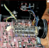
I found a picture that I could see better (and did a little tweaking to the picture so that I could see it better) that shows the FM signal input. The red circles show the FM antenna input and where it connects to the tuner board.
Numbers 1,2,3, and 4 represent CT101, CT102, CT103 and CT104 respectively on the schematic. CT104 (number 4) is the local oscillator trimmer capacitor.
Disregard my earlier post and picture on its location.
Okay, just saw you recent post as I refreshed the page before posting.
That is good information. Good trouble shooting!
It could be as simple as a poor connection (bad solder connection) or a bad physical connection internally to IC202.
You could carefully reflow the solder connections for IC202 and the surrounding components.
Those are the voltages that you would expect to see. Note that one side of the stereo lamp is connected directly to the 15.8 volt power supply rail and it is turned on when the lamp driver in IC202 pin 9 goes low (your measurement of 0.8 volts)
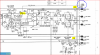
You could look at the voltage on pins 10, 11 and 12 of IC202 and compare them when the stereo light is working and when it is not. There are some electrolytic capacitors around the IC that could be electrically leaky. You could check the value of the various resistors also.
BTW, did I mention good trouble shooting!
I found a picture that I could see better (and did a little tweaking to the picture so that I could see it better) that shows the FM signal input. The red circles show the FM antenna input and where it connects to the tuner board.
Numbers 1,2,3, and 4 represent CT101, CT102, CT103 and CT104 respectively on the schematic. CT104 (number 4) is the local oscillator trimmer capacitor.
Disregard my earlier post and picture on its location.
Okay, just saw you recent post as I refreshed the page before posting.
That is good information. Good trouble shooting!
It could be as simple as a poor connection (bad solder connection) or a bad physical connection internally to IC202.
You could carefully reflow the solder connections for IC202 and the surrounding components.
Those are the voltages that you would expect to see. Note that one side of the stereo lamp is connected directly to the 15.8 volt power supply rail and it is turned on when the lamp driver in IC202 pin 9 goes low (your measurement of 0.8 volts)
You could look at the voltage on pins 10, 11 and 12 of IC202 and compare them when the stereo light is working and when it is not. There are some electrolytic capacitors around the IC that could be electrically leaky. You could check the value of the various resistors also.
BTW, did I mention good trouble shooting!
MrBill—1
New Member
Thanks I Like Music! Feel like a kid who just showed his mom a gold star on his homework assignment. I HATED school.
I don’t know how to check a capacitor but just a bit of research on the interputer will show me how.
Google and YouTube have the answer. The whole internet creeps me out. I know that modern life couldn’t properly function without it but it’s creepy. Just a bit of a dinosaur here I suppose. I tell my wife that if I get a chance to retire I won’t be carrying a smart phone. Just one that makes and receives calls.
Like anyone cares. Whew, that feels better.
I will continue down this path you have pointed me to. Just have to find that old soldering equipment.
I have an old Weller and a couple of Radio Shack irons. I sure wish the shack were still around. They were convenient.
Thanks for the advise Flipper. I believe it is useful also.
I don’t know how to check a capacitor but just a bit of research on the interputer will show me how.
Google and YouTube have the answer. The whole internet creeps me out. I know that modern life couldn’t properly function without it but it’s creepy. Just a bit of a dinosaur here I suppose. I tell my wife that if I get a chance to retire I won’t be carrying a smart phone. Just one that makes and receives calls.
Like anyone cares. Whew, that feels better.
I will continue down this path you have pointed me to. Just have to find that old soldering equipment.
I have an old Weller and a couple of Radio Shack irons. I sure wish the shack were still around. They were convenient.
Thanks for the advise Flipper. I believe it is useful also.
MrBill—1
New Member
I am going to pull the board out and tells the solder at that point.
I guess this will also involve becoming familiar with the cord that wraps around the wheel to move the “fins” that tune in the stations.
Clearing space on the bench. It is about a 50’ wall from the place that I have the receiver in to the bench. This thing is heavy!
I guess this will also involve becoming familiar with the cord that wraps around the wheel to move the “fins” that tune in the stations.
Clearing space on the bench. It is about a 50’ wall from the place that I have the receiver in to the bench. This thing is heavy!
I LIKE MUSIC
Super Member
If you have not done so already, in might not be a bad idea to do the voltage comparisons on IC202 I mentioned above before disassembling the receiver. It may not tell you anything, but it might.
MrBill—1
New Member
I was having a good long look at the receiver just now. I peered through the side of the chassis. I can see the IC202 from the underside of the board.
I took one of my small screwdrivers and pressed sideways on pin 9.
When I turned the unit on the stereo light lit up. It had been tuned to a channel last night.
I switched the mode from stereo to mono and back again. The light came back on.
I tuned to different channels and the light would go off between stations and come on again when tuned into one.
Here is the best picture I could take with the phone. You can see that pin 8&9 are marked on the board.
I am about to measure and record the voltages at each pin.
I took one of my small screwdrivers and pressed sideways on pin 9.
When I turned the unit on the stereo light lit up. It had been tuned to a channel last night.
I switched the mode from stereo to mono and back again. The light came back on.
I tuned to different channels and the light would go off between stations and come on again when tuned into one.
Here is the best picture I could take with the phone. You can see that pin 8&9 are marked on the board.
I am about to measure and record the voltages at each pin.
I LIKE MUSIC
Super Member
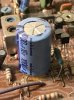
That is glue, it was used to hold the capacitor during the manufacturing process. In some cases it can become corrosive. Most of us remove it. It looks like there might be some corrosion on the jumper right next to the capacitor. I would likely clean it off.
Wow...More great trouble shooting!
You might be surprised how many times that a tool like this (non-conductive to prevent shorts) has been used to probe around a circuit and find the trouble. Since it is non-conductive one can probe around a circuit while it is on and find bad connection issues and so on.
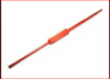
Okay, I am going to admit something here and take the ridicule. I save the caps from ballpoint pens. They make great probes for low voltage application.

It sounds like (okay, sorry for the pun) that melting some solder may be in your future. Hopefully it is just a bad solder connection and not a mechanical issue with the pin inside of the IC.
Be very, very, very careful when measuring voltages. A single slip can destroy parts. Also when reflowing the solder connections. A single unwanted solder bridge where it is not supposed to be can destroy parts.
BTW, did I mention great trouble shooting!
Wow...More great trouble shooting!
You might be surprised how many times that a tool like this (non-conductive to prevent shorts) has been used to probe around a circuit and find the trouble. Since it is non-conductive one can probe around a circuit while it is on and find bad connection issues and so on.
Okay, I am going to admit something here and take the ridicule. I save the caps from ballpoint pens. They make great probes for low voltage application.
It sounds like (okay, sorry for the pun) that melting some solder may be in your future. Hopefully it is just a bad solder connection and not a mechanical issue with the pin inside of the IC.
Be very, very, very careful when measuring voltages. A single slip can destroy parts. Also when reflowing the solder connections. A single unwanted solder bridge where it is not supposed to be can destroy parts.
BTW, did I mention great trouble shooting!
Last edited:
I LIKE MUSIC
Super Member
Sometimes you can see the issue as in the picture below. Notice the ring around the pin in the picture on the left.

Sometimes it can be difficult to see and that is where the probe can come in handy.
Sometimes it can be difficult to see and that is where the probe can come in handy.
I LIKE MUSIC
Super Member
That is glue, it was used to hold the capacitor during the manufacturing process. In some cases it can become corrosive. Most of us remove it. It looks like there might be some corrosion on the jumper right next to the capacitor. I would likely clean it off.
Wow...More great trouble shooting!
You might be surprised how many times that a tool like this (non-conductive to prevent shorts) has been used to probe around a circuit and find the trouble. Since it is non-conductive one can probe around a circuit while it is on and find bad connection issues and so on.
View attachment 1068061
Okay, I am going to admit something here and take the ridicule. I save the caps from ballpoint pens. They make great probes for low voltage application.
View attachment 1068062
It sounds like (okay, sorry for the pun) that melting some solder may be in your future. Hopefully it is just a bad solder connection and not a mechanical issue with the pin inside of the IC.
Be very, very, very careful when measuring voltages. A single slip can destroy parts.
Edit:
Sorry about the double post, don't know what is up with that.
Wow...More great trouble shooting!
You might be surprised how many times that a tool like this (non-conductive to prevent shorts) has been used to probe around a circuit and find the trouble. Since it is non-conductive one can probe around a circuit while it is on and find bad connection issues and so on.
View attachment 1068061
Okay, I am going to admit something here and take the ridicule. I save the caps from ballpoint pens. They make great probes for low voltage application.
View attachment 1068062
It sounds like (okay, sorry for the pun) that melting some solder may be in your future. Hopefully it is just a bad solder connection and not a mechanical issue with the pin inside of the IC.
Be very, very, very careful when measuring voltages. A single slip can destroy parts.
Edit:
Sorry about the double post, don't know what is up with that.
MrBill—1
New Member
Thanks for the hints on the tools.
The stereo issue seems to be stable at the moment. I really don’t want to remove and look at this board right now. I am taking the easy way out for now and leaving it all alone.
I know this isn’t how a professional would handle it but hey, I am a hobbiest. I have a note taped to the bottom of the receiver so that in the future should my son or daughter have an issue (whoever may want it when I am gone) it might give them a head start on resolving it.
If I repair it I will of course remove the note.
Frankly, I don’t think anyone in my family would even attempt fixing a machine. If they have a problem with any device they throw it away or have someone else repair it. I have always enjoyed learning how something works.
I am going to closely watch the Craigslist tools section for items I may need.
I think I will leave the glue alone also.
I liked the Flipper series. Good show.
I always envied the boys out in their small boat. “No one you see is smarter than he”.
The stereo issue seems to be stable at the moment. I really don’t want to remove and look at this board right now. I am taking the easy way out for now and leaving it all alone.
I know this isn’t how a professional would handle it but hey, I am a hobbiest. I have a note taped to the bottom of the receiver so that in the future should my son or daughter have an issue (whoever may want it when I am gone) it might give them a head start on resolving it.
If I repair it I will of course remove the note.
Frankly, I don’t think anyone in my family would even attempt fixing a machine. If they have a problem with any device they throw it away or have someone else repair it. I have always enjoyed learning how something works.
I am going to closely watch the Craigslist tools section for items I may need.
I think I will leave the glue alone also.
I liked the Flipper series. Good show.
I always envied the boys out in their small boat. “No one you see is smarter than he”.
I LIKE MUSIC
Super Member
I am taking the easy way out for now and leaving it all alone.
That is not a bad idea. If, and it is only one possibility, the issue is internal to the IC, then heating the pins might make it stop working all together. In my many years in this field I have seen this happen, although it is not all the common.
It does not get much better than that and you learned about and did a good job of basic trouble shooting.

You can revisit it if the issue returns, but it may continue to work for a long time.
I LIKE MUSIC
Super Member
Thanks so much for your help I Like Music!
It has been my pleasure and I am glad that I was able to help.