• The move to the new server is done. There are some software and database maintenance updates in process. This has us passing the hat around to help out. We appreciate any donations. Seriously, even a dollar helps. The payment page may be found here - https://www.audiokarma.org/support.html

Stopped Building a Tube Amp to... Build a Tube Amp

linuxslate

Well-Known Member
Also known as the "Compromising My Principles build."

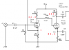
Yes, I'm at it again. Building basic Tube Amps around Switch Mode Power Supplies. The whole purpose of this build is to test the pictured SMPS.

It's a basic P-P stereo power amp based on surplus 6п14п tubes. It is a very low budget build.

Other features (or lack thereof):
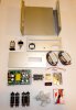
1. Note DAC board. This was a DAC that I rejected for my previous build, but I figured I might as well throw it in this build. I don't recommend these or anything based on a PCM2706. It sounds no better than a PC's audio output (Intel HDA), and there are issues with the PC volume control working correctly on both Windows and Linux. So why use it at all? -- It's more useful built into an amp than in a bin under my bench. -- There's already a square hole in the chassis. -- Having a built-in DAC is convenient.
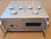
2. The chassis is surplus. That is why it has the cutouts it does. There used to be an LCD display in front. I may order an LED VU meter for it, or I may just leave it out for now. Either way, there will be smoke colored acrylic there. The LED VU meter will be connected to the input, or perhaps between the driver and PI, it won't actually be measuring power output or anything. I'll try to adjust it so that the Red LEDs do reflect onset of saturation/clipping. -- Solid State input of VU meter connected to audio signal -- Principles - Compromised.
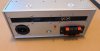
3. The long slot on the back panel will have a mesh screen behind it so that it acts an ventilation. The RCA input jacks will be in that area, too.
4. I'm using a tiny toggle switch to select the RCA inputs or the DAC. The input switch will be on the back panel. I don't like passing audio through toggle switches (Principles - Compromised.)
5. It will probably use cathode biasing. (Principles - Compromised.)
6. Hardware and discrete components will be picked during the build, and are not shown.
7. It will have handles on the front, and will overall look very much like a cheaper version of my previous build. I forgot to put the handles in the picture.
8. Both parts and component values are subject to change. (for example the big, ugly toggle switch). If I find a prettier power switch, I'll use it.

I will detail my testing of this SMPS in my "Modern Power" thread. Lot's of people have already provided their comments on using SMPS's in tube amps. I (and probably the moderators) would prefer if we do not do that here. Useful information on SMPS's can go in the other thread.

What is appropriate here (and requested) are comments on the rest of the circuit. Please note that the build is obviously in an early stage. So is the schematic. Many component values are simply based on what I have on hand, and may change as the design progresses.
Tube_amp_6p14p_parts_2.JPG
 

Attachments

Register to hide this ad
Compromise on your compromise: EFB using an LM337 regulator will give you what is effectively fixed bias without a negative DC supply.

any special reason for bringing the feedback into the grid rather than the cathode of the voltage amp?
 
1. The input coupling capacitor is too small, into the 470k grid resistor and 100k negative feedback resistor in parallel, it is -1dB above 70Hz.

2. The 470k plate load of the first half of the 12AX7 seems too high, it will probably roll off the highs into the miller capacitance of the second 12AX7 grid.

3. I agree with gadget about connecting negative feedback to the cathode rather than the grid of the first 12AX7. The problem with the present connection is the amount of feedback can be affected by the source impedance of the source connected to the input, since feedback is determined by the ratio of the 100k resistor to the 470k resistor and source resistance of the source in parallel. Speaking of this, see comment 1.

4. The 100pF capacitor value may need to be adjusted once the amplifier is built

5. I would probably reduce the grid resistors of the output tubes a bit to reduce the chance of thermal runaway if you get a marginal output tube and then increase the coupling capacitors to say 0.1uF
 
any special reason for bringing the feedback into the grid rather than the cathode of the voltage amp?

Ooops. That's purely a drawing error. That would be positive feedback, and probably lead to all sorts of unpleasantness.

I'm still looking at various methods of Bias, including "typical" EFB circuits.

Obviously, there is also the same (+/-) converter board I used in my last build. I'd need to buy more because I used the other one I had in a (non-tube -- Op amp) project.

Another Idea was to use a small, separate 24V SMPS, and simply connect the (+) to the HV supply ground. I'd then use a simple pot connected as a voltage divider to make the desired (grid) bias (or bias's). This should work fine since both power supplies are isolated. The tiny 24V SMPS, has the same wide input voltage, so it would still work the same no matter the line voltage. It's also supplying nearly no current, so one would think it would outlast the 300V supply.

Thanks to an unrelated and unintended project involving my clothes dryer, I now have a supply of relays that would be perfect for a loss-of-bias shut-off.
 
@maxhifi :

The drawing error should alleviate the concerns about 1) and 3). The global feedback is connected to the cathode in the usual manner.

2) Hmmm... It's actually worse than that because the grid leak resistor shown (R12 - Currently 1K) is really supposed to be much larger (on the order of 10K - 100K). In my last build I needed a large resistor in there to make the amp stable. -- I needed more effect from the miller capacitance. Also, 1K on the grid of a 12AX7 is pretty much nothing. According to my notes, all of the resistors are much larger in that area on my previous build. I'll have to look at my previous amp to verify the values. I think I have some more math to do in that area.

4) Yes. I will tune the feedback after the amp is up and running.

5) Wouldn't it really be the values of R8 and R9 that I need to decrease to prevent thermal run-away? I guess these are the resistors you are talking about, and not the 1K grid resistors. 470K is well in-spec for a 6BQ5, especially in P-P, but maybe I should go lower for very old (likely gassy) 6P14P's. I'm pretty sure I can go down to (e.g.) 270K without loosing any bass, but again, a little math won't hurt too much. :(
 
Lots of things (see Fisher) had a wire from plate to grid on this style of inverter. This is from a Fisher Philharmonic, but its plenty close enough for demonstration

Fisher circuit.jpg


Might actually be better to put the Miller resistor between the input jack and the voltage amp. A big part of that equation is the gain of the stage, and a split load inverter is slightly under 1.

If you're bringing the feedback into the cathode, it will need a split resistor there too.

the smaller grid resistors at the output tube would mostly be of use if you got a gassy tube or one with grid leakage. A smaller resistor would make it more difficult for the grid to start going positive and causing the tube to go stupid. Those would be R8 and R9.

also typically your grid stop resistors go on the other side of your grid to ground resistors, so R6 and R7 should shuffle over closer to the output tubes.
 
The output stage grid resistor (R6 and R7) location was a drawing error, too. I know they go directly to the grid pin with short leads, and nothing else on that pin.

I'll stick with DC Driver/PI coupling for now. I'll start building up one channel, and see if I can get them to bias correctly.

Thanks for the help and encouragement.

I'm not going to post every step, but when/if I get some progress, I'll post a picture or 2. For now, I plan on some quality time with my drill press.
 
Despite some strange work hours, I have made some progress with this build:

IMG_20210130_2_ed.jpg IMG_20210130_1_ed.jpg


Notes:

-- The area on the front panel where the LED VU meter will be looks blue. That is due to the protective film still on the Smoke colored Lexan. The LED VU meter should arrive this week. The piece of perfboard that will support the meter is already installed behind the Lexan panel.
-- There is currently no fuse holder. I keep changing my mind on this. There is a fuse soldered onto the SMPS board. I have several fuse holders in my bin, and several caps, but none of the caps fit the fuse holders, so I decided to just go with the on-board fuse holder. Then I decided to buy a fuse holder. Then I decided it would make the back panel too busy, and put AC too close to the DAC board. But it really should have...o_O I can't decide if I am capable of making simple decisions or not. :eek::crazy:
-- I'm really trying to keep the cost down. I was too cheap to use grommets where the transformer wires go. Those white things are vibration dampers from drone camera mounts, each cut in half.
-- As my other builds, I am painting the OPT's. That is why they are not installed in this picture.
-- I haven't done any wiring yet, nor have I done any work on the schematic. I can do the basic wiring of the AC input, power switch, etc., and then re-visit the actual circuit before I start building.
 
Last edited:
Most importantly, I forgot to mention that this is a re-utilized, surplus chassis. That is the reason for some of the strange cut-outs and placement of some items.

For example, there used to be a small fan where the IEC connector is.
 
have one of those IEC sockets with a built in fuse? I've salvaged those from things before. Not much larger than a standard IEC so it won't hog much space on the back
 
have one of those IEC sockets with a built in fuse? I've salvaged those from things before. Not much larger than a standard IEC so it won't hog much space on the back

There is one of those in my previous build. It came with the chassis, which included the appropriate cut-out. In that case, the IEC socket included the fuse holder, but not a filter. I think I'm safe enough with the PC board fuse, but my next build will definitely include a rear-panel accessible fuse.
 
so long as there is a fuse somewhere between the power cord and the guts I'm generally fine with it. Spent too much time working on old stuff that came with nothing to have any particular fondness for the idea of skipping them entirely. I have hidden fuses inside of things that I didn't want visible external mods on though.
 
Glow Test:

IMG_20210205_sm.jpg

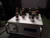
Powered up for a glow test.

There is definitely some strangeness with the Switch Mode Power Supply, and I had to have a dummy load on the B+ output to get the right voltages for the heaters. The details are in my SMPS thread.

The variation in glow is real. Those are non-matched Reflektor 6п14п's. I tried to pick 4 that were close in year of production, and tested similarly on my relatively dumb tube tester. More of the filament can clearly be seen on that one that is bright on the bottom. Hooray for tube bottom-feeding !!

Note that not even the pilot light is connected yet. The resistor for the pilot light will be on the LED VU meter support board, and the LED VU meter has not arrived yet.

@gadget73: It still does not have a separate fuse yet, but it will. I'm hoping to find something smaller than a full-sized panel mount holder. I'll buy something on my next trip to the local surplus electronics store.

I'm going to look at the schematic a little more, and then slowly start wiring one channel.
 
IMG_20210206_1_sm.jpg

The local surplus place came though for me. This takes a standard fuse but extends less into the chassis than the "marine grade" one from Ace, and it cost less than 1/2 as much.
 
As previously mentioned, I have been working very slowly on this amp.

I've updated some component values base on a (very) little math, but mostly based on parts actually on hand. In fact I have literally spent more time sorting resistors than I have building.

actual.png

I built up one channel's Concertina stages, and the values indicated in red are actual values (Point 'B' is 270V).

Again, this is an SMPS powered project, but for this bench test of only these stages, power was supplied by one of the smaller "70W" adjustable 12V --> 300V boost modules. This actually worked out really well, as my bench supply provided the 12V for both the series-wired heaters and the boost SMPS. The bench supply essentially works to current limit the high voltage too. Any unexpected load on the HV will effectively shut down everything as long as the bench supply current limit is set appropriately.

The point is -- Even if you are still 100,000% opposed to using an SMPS in audio equipment, you may want to look into these modules as an inexpensive bench HV supply. The multi-turn pot gives excellent voltage adjustment, and the combination of it's inherent limited current, current limiting of the 12VDC source, and the double isolation make it safer for both component and human than running some massive transformer and the much higher energy storage necessary with a linear supply.

The pace of building should pick up a bit now, as I have most other parts "kitted up". There may be a delay if I have to order power resistors.

No pictures of my wiring... If the cat had a hairball on the same section of the other channel, you wouldn't be able to tell the difference.
 
kind of a shame the one amp I had that lacked an HV supply has been moved on to another home for use as a parts donor. It had an onboard heater and bias supply, but the B+ source was offboard for whatever reason. I had knocked something together but it would have been a perfect candidate for an SMPS.
 
Lots of things (see Fisher) had a wire from plate to grid on this style of inverter. This is from a Fisher Philharmonic, but its plenty close enough for demonstration

View attachment 2101186


Might actually be better to put the Miller resistor between the input jack and the voltage amp. A big part of that equation is the gain of the stage, and a split load inverter is slightly under 1.

Gain of a split load depends on how you measure it. For two identical triodes, it is hard to beat for gain. In this case gain of the first section is going to be 70-80, and then you keep most of that when creating the two out of phase signals. So a split load is very like a 1:.9+.9 transformer... :)
cheers,
Douglas
 
If you want to measure it plate to cathode i guess its more than slightly under 1, but its still not going to be as high as the voltage amp in front of the inverter so the Miller capacitance will also be considerably less. If the idea is to make a simple low pass filter with an R and the Miller C, then you want the resistor ahead of the section with the most gain.
 
The resistor marked "Omit?" is not in the circuit. There's just a wire in there now. I included it in the drawing because I had to add that to another build to keep it stable. Also several sites (Valve Wizard?) were adamant about using grid stoppers everywhere. If there is any hint of instability, I'll try a resistor on the gain stage first.
 
An update on this build.

One channel is up and running, and sounding pretty good. The LED VU meter is installed and working, as is the DAC and input selector switch.

I've been fighting a significant 60Hz buzz, which is ironic for an SMPS-powered amp, but that's what I've got. I've been able to significantly reduce the buzz, but mathematics says I can halve the amount of buzz forever, and still have a buzz. It feels like that is exactly what I am doing.

Things that have helped (in order of buzz reduction):

1. A 1µF capacitor between the heater return and the B+ return. The a listing page for the SMPS says the returns must be kept separate. Interestingly, there does not seem to be any difference in leaving them separate, or hard connecting them, but the capacitor helps significantly.

2. Adding the (planned) global feedback. Note that this significantly reduces gain overall, so that is part of it, but it really helps reduce the buzz when the amp is idle.

3. Adding a capacitor at the end of the 6.3V heater string.

The buzz definitely seems to be associated with the heater (12.6V and 6.3V) volt outputs.

Note also that I am only running one channel at the moment, so the other tubes are not installed. Adding the tubes for the other channel increases the load on (especially) the 6.3V source, and thus increases the buzz again.

When probing around with my scopemeter, I see a 48Khz switching artifact everyplace, but what ends up on the speaker terminals is clearly 60Hz. It was over 500mV into 8 ohms before the above mitigation steps.

With the mitigations in place, I've got it down to the minor irritation level. It's not noticeable with music playing, and with the speaker a few feet away, the fan in the PC on my desk makes more noise than the 60Hz, but it's still not something that anyone would call "acceptable" for what is supposed to be a HiFi amplifier.

Other general comments: It's sounds OK otherwise, with plenty of low end. It may need a little input attenuation. 70% on my PC line (not headphone) seems to over drive it in terms of both the volume I would expect out of a 6BQ5 (equiv) amp, and the onset of distortion.

It looks "OK" with a square wave input, given the level of effort I plan on putting into this build, and expectations for a small amp. I'll try to upload some waveforms of the buzz and square wave response next time I get to work on it.

In the mean time, attached is a schematic with as-built component values.

Schematic notes:

1. The OPT's have 8K and 10K primary taps. I am using the 8K taps, the 10K taps are capped and stowed.
2. The OPT's have 4,8, and 16 ohm outputs. The 4 and 8 ohm taps are wired to the speaker terminals, the 16 ohm tap (not the 8 ohm tap as shown) is used (only) for the feedback.
3. Feedback cap value is actually 180pf.

Plan: Build up the other side, possibly tweak input and feedback as needed.
 

Attachments

Back
Top Bottom