• The move to the new server is done. There are some software and database maintenance updates in process. This has us passing the hat around to help out. We appreciate any donations. Seriously, even a dollar helps. The payment page may be found here - https://www.audiokarma.org/support.html

Strain Gauge catridges

We got dox!

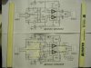
Here's the skiz' for the original ckt and the mod'ed ckt.
The first is a comparative shot, the 3rd for the PS section which is untouched.
The upper section is the right channel and the lower section left channel. The bias polarity is minus for the left channel and postive for the right channel, this is important to maintain correct absolute acoustic polarity (non-inverting) for this set-up. The signal amp stage uses the OPA2604 and the PS amp the NE5532.
 

Attachments

  • IMG_0130.JPG
    IMG_0130.JPG
    105.4 KB · Views: 193
  • IMG_0132.JPG
    IMG_0132.JPG
    98.4 KB · Views: 158
  • IMG_0133.JPG
    IMG_0133.JPG
    106.3 KB · Views: 368
  • IMG_0135.JPG
    IMG_0135.JPG
    102.7 KB · Views: 365
  • IMG_0138.JPG
    IMG_0138.JPG
    120.2 KB · Views: 167
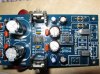
Board porn

Nudies of a mod'ed board.
Carefully note position of jumpers in place of some removed components.
The output limiting resistors in place of the output blacking caps and the 3.0k resistors on the bottom are additions not taken from the kit. If 47k resistors are subbed for the repositioned 20k LF roll-off loading resistors, they too must be added. Note that the repositioned 1k/100k FB loop resistors are repositioned from the front end of the original ckt and the 20k from the original FB loop, 47k loading will put the LF roll-off well-into the warp region.
 

Attachments

  • IMG_0101.JPG
    IMG_0101.JPG
    60.3 KB · Views: 104
  • IMG_0102.jpg
    IMG_0102.jpg
    59.4 KB · Views: 117
Last edited:
Helo Pio1980, Thanks for the advice!
Do you think I'm being overly concerned about mechanical or electrical interactions with the transformer in the same box with the circuit?
It would be easier for me to keep the existing arrangement I have,and put it all together in one box.
Or do you think there would be audible benefits for isolation?
Bst regards, DM

I just noise-checked the new box in the system and while it is a bit polarity sensitive re the AC plug orientation as can be expected, the best orientation gives no hum and a noise floor sufficiently below signal to be a non-issue.
So I'd call this compact and rather elegant packaging a success.
 
By the way, thinking about the Soundsmith cartridge... I always thought that probably it was based on some of the Panasonic's SG cartridges' technology.

I invite you friends to check out these links, it won't take you more than 1 minute to check them out:

http://www.stereophile.com/ces2006/010606soundsmith/index.html
http://www.positive-feedback.com/Issue25/images/P1010252.jpg
http://www.positive-feedback.com/Issue25/he2006b.htm

Looks familiar?
SURPRISE!!

Looking forward to your comments.

Just remember SG carts can be light sensitive! :sigh:

I shine a little flashlight on mine and it gets noisy!
Very interesting, when you look at the pics above (Soundsmith prototype). Maybe that blue light is totally intentional, maybe it reduces noise or increases the resistance of the beams... Who wants to experiment?
 
Not suprized, his present carts look like the Matsushita cart's layout with a more rigid housing and I expect, refined details uneconomical in the original. I also think the blue LEDs may be current limiters for the elements as well as power-up indication.
 
I bet the blue light is handy for cueing too...

I'm considering opening up one of my EPC-450CII cartridges and documenting the process. I've already opened up one, to fill the internals with silicone, but i haven't opened it up completely; just the top plate.

But yesterday i found that the one i was using had something loose, since one of the channels resonated when the cartridge was tapped, and bass response was audibly weaker than the other EPC-450CII cartridge i used for comparison.

By the way, i've been carrying some amateur frequency response tests, and it seems that a low pass filter (6db/oct) with the cutoff frequency at 7000Hz will make the high frequency response flat within +/- 1dB.

Still need more testing to do.
 
Never got the chance to test a Technics EPC-4xx out but saw one on the web with channel issues.
Do the resistance of the channels balance?
 
Here's the skiz' for the original ckt and the mod'ed ckt.
The first is a comparative shot, the 3rd for the PS section which is untouched.
The upper section is the right channel and the lower section left channel. The bias polarity is minus for the left channel and postive for the right channel, this is important to maintain correct absolute acoustic polarity (non-inverting) for this set-up. The signal amp stage uses the OPA2604 and the PS amp the NE5532.

Hallo Pio1980

Your circuit is working as per righthand schematic?
You are speaking of 2 Op amps.
I see your gain of the NE5532 has already a gain of 100 or do you need the second OPA amp for the equelization?
Otherwise the first amp will do for headphone or input to AUX of your Amp.
Your NE5532 has a gain of 100 by the 1k and 100k resistors
Just received the EPC450C with 4 channel diamond stylus, that should be a shibata. By the way I use it for stereo. The equelization is accomplished by my amplifier which has low, mid, high controls compensation just on the right place.
Read on the web/forums need tracking force of 2.0 or 2.3 grams.
That would be no harm because of greater contact surface.
Am I right ?
 
Hallo Pio1980

Your circuit is working as per righthand schematic?
You are speaking of 2 Op amps.
I see your gain of the NE5532 has already a gain of 100 or do you need the second OPA amp for the equelization?
Otherwise the first amp will do for headphone or input to AUX of your Amp.
Your NE5532 has a gain of 100 by the 1k and 100k resistors
Just received the EPC450C with 4 channel diamond stylus, that should be a shibata. By the way I use it for stereo. The equelization is accomplished by my amplifier which has low, mid, high controls compensation just on the right place.
Read on the web/forums need tracking force of 2.0 or 2.3 grams.
That would be no harm because of greater contact surface.
Am I right ?

Not quite. The first NE5532 ckt, unmod'ed, is the noise cancelling servo amp for the regulator section,
attachment.php

the second uses an OPA2604 with the 100k/1k fb network, it is the linear 100x gain stage for the cart. They are not cascaded.
attachment.php

Hope this clears it up for you.
I am working on a second stage board to be piggy-backed on this interface/pre to provide EQ as per this thread on another forum;
http://www.vinylengine.com/turntable_forum/viewtopic.php?f=19&t=28750&start=315

1.8-2.0 gm TF is good, a bit more if your situation and ears say so.
 
Last edited:
Flavio here!! Hi fellas!!

For the ones who just arrived to the thread and need a quick and dirty preamp:

dnosjq.png


NOTE: This preamp is to be powered using 9V batteries. Do not use a power supply since if something fails in the power supply and the voltage goes way up, or there is a power surge... bye bye strain-gauge elements!!

Note the "15Hz hi-pass section" has been wrongly calculated by me. And thus it is seriouly lacking in the bass department. Change the resistor or the capacitor to a higher value (for example 2X the value). Experiment.

Of course it needs more improvements. Suggested:
- Another "balance" control (for the other channel)
- Have both strain gauge elements conected to the same +V supply and invert one of the channels using an additional opamp.

It works OK with TL072 and TL082 opamps. Noise is not intrusive.
Sound quality is good and clear as a strain gauge cartridge should sound (once you correct the "hi pass filter" for better bass). Satisfaction guaranteed.

I'm pretty sorry i cannot draw an updated schematic, i've been very busy lately. But i promise i will draw a better preamp... at least within this year ;)

Sorry, what was really wrong on my schematic was C1. C1 is removing all the bass content. Just delete it or increase it to a way bigger value, like 1uF (you have to use a very good non-polarized capacitor in this case).

It still works, of course.

I'm still preparing a much more improved version of this preamp. A dramatically improved version, with special equalization. Stay tuned!
 
You mean my equalizing circuit? It is still untested, only simulated...

Not since you withdrew it, I had a couple other options one of which was Hypnotoad taking an interest in the project as he has with the quite-good mag/MC front ends he's done.
 
Back
Top Bottom