• The move to the new server is done. There are some software and database maintenance updates in process. This has us passing the hat around to help out. We appreciate any donations. Seriously, even a dollar helps. The payment page may be found here - https://www.audiokarma.org/support.html

Strange capacitor Sansui AU-719 Power Supply

SansuiJavier

Active Member
Hello everyone,
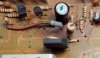
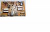
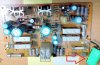
I have started to restore a beautiful sansui AU-719, and it seems that someone repaired it without much care. On board F-3101 there is connected a 1000 uF / 50 volts capacitor. Does anyone know why it is there and what function can it have?
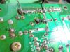
The C-615 was replaced by a 220 / 63v, but I see that it was placed correctly (however I am going to change them all), it is also seen that in the area of R639 there was a lot of heat at some point.
I would also appreciate it if you could help me find other components that could have been damaged on this board.
Thanks !!
a2audiokarma.jpg a3audiokarma.jpg a5audiokarma.jpg tarjeta F-3101a.jpg
 
Register to hide this ad
That green capacitor has no business being there - added by someone who doesn't know what they are doing by the looks of it.

The two 68Ω resistors (R634 & R635) will get VERY hot, there doesn't seem to be a cure for this, it's a feature of the amplifier :) - just try to fit replacements that don't look ugly when a bit overheated. (NB: if they really burn up - you have a fault).

Lastly - and I seem to mention this a lot - C615... you seem to have noted the issue regarding C615 (I think it is) where the silk screened polarity marks are incorrect on the PCB. Please check that I have indicated the right capacitor, and verify polarity before installing a replacement. ;)
 
Last edited:
Thank you Hyperion, I will have care with the C615, I am going to reconstruct the board and to replace the damaged components. I would like to verify the power supply without damaging other components of the amplifier, how I can do it once the board is restored?
 
how I can do it once the board is restored?

I haven't done this myself but you can leave many of the board power connectors (Tone, Phono/EQ and Driver boards) unplugged when you power on, this will give you a chance to measure all the supplies and verify they are as they should be. Then you could plug them in one board at a time, with meter(s) already connected - checking those voltages as you go? however, you should connect all the grounds. And power off after each measurement and before each connector plug in.

Just an idea if you are a bit nervous about a PSU fault damaging your work. ;)
 
Last edited:
I haven't done this myself but you can leave many of the board power connectors (Tone, Phono/EQ and Driver boards) unplugged when you power on, this will give you a chance to measure all the supplies and verify they are as they should be. Then you could plug them in one board at a time, with meter(s) already connected - checking those voltages as you go? however, you should connect all the grounds. And power off after each measurement and before each connector plug in.

Just an idea if you are a bit nervous about a PSU fault damaging your work. ;)
Thank you, it is as I imagined, because I have not done this by stages before, I will be careful. It is by precaution, I have read that sometimes they can damage the output transistors when recap the power supply, and I prefer to keep them safe:beerchug:

I hope you have better solder techniques than the previous rookie.
I hope so too;)
 
Back
Top Bottom