• The move to the new server is done. There are some software and database maintenance updates in process. This has us passing the hat around to help out. We appreciate any donations. Seriously, even a dollar helps. The payment page may be found here - https://www.audiokarma.org/support.html

Strobo vs no strobo

I'm not sure what's going on with that circuit.
Easy enough to check accuracy using an external light source against the strobe dots.

Sorry for the confusion .. just wish to be educated if the strobe of my dp-80 is the mentioned mains frequency driven or quartz driven that I am reading here. With apology and cheers.
 
Sorry for the confusion .. just wish to be educated if the strobe of my dp-80 is the mentioned mains frequency driven or quartz driven that I am reading here. With apology and cheers.
Sorry, I really don't know. I don't understand what the transistors are doing in that circuit.
 
(...) I read that it uses the magnetic strip in the inner side wall of the platter to strobe. (...)

Uhm, no, the magnetic strip in combination with sensors, that read it, provide the "is speed" signal (plus reverse rotation detection) for the speed control - to be compared with the quartz-referenced "shall speed", so that the motor speed can be regulated accordingly.

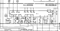
Well, and if your strobe only sports 1 row of marks, but works for both 33 1/3 and 45 rpm, that's a sure sign, that its light is not tied to mains frequency, but also controlled by the control circuitry. And if you follow the trace from the base of transistor TR5 via connector J5 to pin 17 (alias "ST-OUT") of IC1 in the schematic, you can even see two strobe frequencies mentioned a bit above next to that trace. So the strobe light is indeed provided by the quartz-referenced control circuitry.

Greetings from Munich!

Manfred / lini


edit: typo extermination *sigh*
 
Last edited:
Sorry for the confusion .. just wish to be educated if the strobe of my dp-80 is the mentioned mains frequency driven or quartz driven that I am reading here. With apology and cheers.
1708638596753.png


Pin 17 of this IC generates the strobe signal. So the signal does not come from the mains AC line frequency. The frequency is generated from the IC. And,btw, varies if the turntable is on 33RPM versus 45RPM.

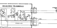
This signal goes to R29/C22 on the diagram below:

1708638669667.png

... the transistors are there only to drive the stroboscope.
 
Well, and if your stobe only sports 1 row of marks, but works for both 33 1/3 and 45 rpm, that's a sure sign, that its light is not tied to mains frequency, but also controlled by the control circuitry. And if you follow the trace from the base of transistor TR5 via connector J5 to pin 17 (alias "ST-OUT") of IC1 in the schematic, you can even see two strobe frequencies mentioned a bit above next to that trace. So the strobe light is indeed provided by the quartz-referenced control circuitry.

Exactly.
 
Back
Top Bottom