• The move to the new server is done. There are some software and database maintenance updates in process. This has us passing the hat around to help out. We appreciate any donations. Seriously, even a dollar helps. The payment page may be found here - https://www.audiokarma.org/support.html

Stromberg-Carlson ASR-333

tekuhn

AK Subscriber
Subscriber
Hello,

I'm working on an ASR-333. At first glance it appeared to be completed stock - all the original paper electrolytics are still there. The only obvious modification was the output transformers have been replaced with a pair of Triad S-146A's. My initial plan was to replace all the electrolytics and also the mismatched coupling caps that had 3 of one brand and 1 of a different brand. After that, I can let it play and deal with any issues that testing reveals. Parts arrived today so I got started on it.

Right off the bat I noticed that the first dropping resistor in the power supply was different. The schematic calls for R44 as 2.2K 5 watt, but what was actually installed was a 1K 5 watt. It certainly appears to be original.

The next difference I noticed was that the negative feedback is supposed to be off the 16Ω tap, but is actually on the 8Ω tap. I'm wondering if whoever changed the OT's moved the feedback in an attempt to adjust the circuit for the different primary impedance of the Triads.

I'm looking for comments as to whether there might be different versions of the ASR-333 and maybe I don't have the correct schematic? Despite the 25 watt handling of the Triads, the unused ultralinear taps, and the lower primary impedance (6600Ω vs. 8000Ω) - should the Triads be OK without other mods for them to work at their best?

Thanks for any help!
 
Register to hide this ad
See if @Tom Bavis page has the right one.

Looks like the ASR-433 has the neg feedback taken from the 8 ohm tap like this amp does so I’ll check to see if the other components match as well. I wonder if the change to the 16 ohm tap was an improvement in the design stability and performance? My amp also had the 50uF doubler caps and not the 100uF as shown. I replaced with F&T 220uF which were about the same size.
 
Hard to say but with different transformers the feedback likely needs to be re tuned anyway.
 
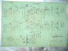
Hope this helps. It's from the bottom plate of mine. Took a photo but I think most things are legible.
ASR-433 schem on cover 3 IMG_1349.JPG
 
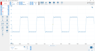
I found that the feedback tuning of the power amp section could be improved with some measurements and adjustments. A phase advance cap across the feedback resistor and a shelf network on the input stage plate resistor.

Was able to get this 10k square wave performance from just the power amp section.
ASR433 chan B 10kHz 50k_22p fdbk 22k_47p shelf.png
 
Comparing these various 333 and 433 schematics, my circuit is pretty much identical to the ASR-433. It has 50uF doubler caps, the first power supply dropping resistor is 1K 2W, and the feedback line is connected to the 8Ω tap. I assume it is an early 333 and they must have changed the later units as shown in the 333 schematics.

I also do not see hum balance pots anywhere. I haven't traced the wires yet, but assume there are a couple fixed resistors with the cathodes connected in the middle of the divider. not sure if that is from the factory or if someone modified it in the past.

Thanks everyone for the input!
 
The hum balance pots in mine were bad, but they live towards the back and have holes in the chassis for a screwdriver to adjust them. Fairly chunky and obvious, you'd be hard pressed to miss them if they are installed.
 
The 333 schematic that you posted matches the baseplate schematic from my 533, exactly.
And that schematic matches the components used in my 533, which I have refurbished with new caps and replaced out of spec resistors.

Specifically, to your questions:
R44 is shown as 2.2K, 5W
Neg feedback is off the 16 ohm tap
The hum pots are shown on the schematic and are present and functioning in my unit. Someone must have removed yours and replaced with a voltage divider, as you mentioned.

Best of luck on your project, I own (2) 433's and a 333 and they are my favorite amps (paired with Altec Valencia's)
Please continue to post your findings, it will be helpful to all of us.
 
More strange findings....

There are two holes in the chassis between the EL84 pairs that I assume should be the location of the hum balance pots. There are no pots and no evidence that there have ever been any mounted - no scrapes or marks in the zinc whatsoever and no silkscreening labeling the holes. The heater windings from the PT are connected directly to the closest EL84 sockets of each pair. On top of that, the cathodes of those sockets are jumpered directly to the heater pin beside it (pin3 to pin4) with a wire link. This is the equivalent to adjusting the hum pot all the way to one side.

Again, I see no evidence that this has been messed with. Is it possible that the early 333 came this way from the factory? I have not listened to this amp yet and have no idea if there is a hum issue or not. Looking for recommendations of whether to try it as-is and see, or whether to add pots or just pairs of 50Ω resistors and attach the cathodes in the center?
 
My unit has hum pots in those locations which are riveted to the chassis. The schematic shows the the wipers connecting to the EL84 cathodes of the relevant channel for a bit of DC elevation.
 
My unit has hum pots in those locations which are riveted to the chassis. The schematic shows the the wipers connecting to the EL84 cathodes of the relevant channel for a bit of DC elevation.
Right - my chassis has the two larger adjustment holes and the 4 small rivet holes, but no evidence there has ever been any pots installed. I think I'm just going to give it a listen once I get the basic overhaul completed. If it's quiet then great, if there's hum then the pots might go in.
 
That is certainly a very nice amplifier, made nicer with those really good output transformers, assuming you can verify the feedback tuning.

Right off the bat I noticed that the first dropping resistor in the power supply was different. The schematic calls for R44 as 2.2K 5 watt, but what was actually installed was a 1K 5 watt. It certainly appears to be original.
Ideally, for the highest power output, you will want to measure the voltage at the 6BQ5 plates once the output transformers are up to temperature, then adjust the value of that first dropping resistor so that the screen voltage is equal to the at-temperature plate voltage. If the screens are too low, you will just be sacrificing power, so that may explain why they dropped that resistor from 2.2K to 1K. You should also consider placing a small value resistor, say 100 ohms, between the screen supply and the two screens for each channel, close to the screens, to prevent any parasitic oscillations there.

The next difference I noticed was that the negative feedback is supposed to be off the 16Ω tap, but is actually on the 8Ω tap. I'm wondering if whoever changed the OT's moved the feedback in an attempt to adjust the circuit for the different primary impedance of the Triads.
Where the feedback signal is taken is not important, but it will change the amplitude of the feedback signal, and with these different output transformers you will want to re-evaluate and re-tune how much negative feedback is being applied. I walk through this procedure in several of my build threads that I can point you to and answer any questions if needed- basically you want to measure the open-loop gain with no feedback resistor, calculate how much negative feedback you want, install a temporary pot and switch to adjust the feedback resistor while switching back and forth between open and closed loop to find the right value, install a fixed feedback resistor of the determined value, then look at square wave response and high frequency amplitude response to determine what amount of feedback compensation capacitance to add in parallel with the feedback resistor.

Despite the 25 watt handling of the Triads, the unused ultralinear taps, and the lower primary impedance (6600Ω vs. 8000Ω) - should the Triads be OK without other mods for them to work at their best?
These high end transformers will give you absolutely spectacular results if you can do the above tuning, otherwise you are casting the dice and hoping. You have some really enviable options here- You can use the ultra linear taps if desired, in conjunction with global negative feedback, but I will defer to the experts here who have more experience with UL- I'm not so familiar with that mode. The the pretty low output impedance of only 6600 ohms (I'm thinking these would have been better in a 6L6 PP) it will be interesting to see the waveform performance when you push it to maximum power- you will want to see if it clips equally at both the high and low extreme- and possibly adjust the cathode resistor to adjust your bias point to center it. As is, it is probably fine. You will certainly get more power out of the transformers with this low primary impedance.

On top of that, the cathodes of those sockets are jumpered directly to the heater pin beside it (pin3 to pin4) with a wire link. This is the equivalent to adjusting the hum pot all the way to one side.
Yeah- I would fix that- put a couple of 220 ohm resistors, one from each side of the filament supply to the 6BQ5 cathode. By elevating the filaments to be centered on the cathode voltage, the two 220 ohm resistors being equal will provide plenty of hum elimination, no pots needed. IF it were my amp, and you already have holes for pots, I would probably add some 2W wire wound pots like these 50 ohm or the like in series with a 120 ohm 2W resistor in the cathode of each channel so you can adjust the operating point and match the bias of the two channels.

What ever you do, you have some great bones to work with.
 
Thank you for the detailed response. Unfortunately, I do not own this amp and I’m just getting it to a level of reliability and playability for an acquaintance. Ultimately, if he decides it’s not his cup of tea maybe I will end up with it.

As for the power supply dropping resistor and feedback tap differences, I can’t tell which version is newer. I tend to believe the 2.2K and 16ohm tap version is newer. This version also shows a .01uF cap by the power switch which is absent on the other version (again leading me to believe the cap was a newer design improvement).
 
6.6k is definitely on the low side for a 6bq5, though higher screen voltage will help it be able to drive them. UL may be even better honestly, it should allow for use of a lower impedance and it also gets around that whole screen supply nonsense.

Fixed bias would also help here but no bias supply exists. Maybe EFB could stand in and get you there.

the hum balance pots are minimally useful, a pair of resistors will do just fine. In a 333 I wouldn't be surprised if it just had resistors, the hum pots would mostly only affect the phono preamp which you don't have. Its not that special anyway so no great loss if I'm being honest. I rebuilt mine as a phono stage from a Harman-Kardon A500, and it now has a DC supply because I couldn't eliminate the hum entirely. I also had to do something with the signal grounding on the phono inputs but I'm drawing a blank right now on exactly what I did to fix it.
 
The level of reliability and play-ability for your acquaintance will depend upon either your tuning, or the skill of whoever changed the output transformers. The output transformers were changed correct? I don't believe this amp came with the Triad iron. If the acquaintance does not want to motivate you to make this amp all that it can be, perhaps you can dissuade them, and do this tuning for yourself. Either way, the path to greatness is well understood and has been laid out.

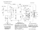
At this point I would not worry about what version the amplifier is, and make it the best it can be. Enhanced Fixed Bias (EFB) is an excellent fit and an easy, huge, performance win with the 6BQ5, and there is a schematic for the Magnavox 9300 (attached) that can be highly leveraged. With the EFB, the feedback tuning I have discussed, and these most excellent output transformers, you have a clear path to a most excellent high-end-class high-fidelity performer for not much work. If your friend does not want to do this, I recommend you acquire the amp and you will never regret it.

I have built the 9300 according to the attached schematic, let me know if you are interested, and I can give you quite a lot of detail. It's pretty easy.
 

Attachments

  • DCG_9300_Channel_Schematic.jpg
    DCG_9300_Channel_Schematic.jpg
    92.3 KB · Views: 15
Back
Top Bottom