• The move to the new server is done. There are some software and database maintenance updates in process. This has us passing the hat around to help out. We appreciate any donations. Seriously, even a dollar helps. The payment page may be found here - https://www.audiokarma.org/support.html

Stromberg-Carlson ASR-333

I continue to find that this amp circuit matches the ASR-433 schematic that Tom Bavis has on his website. The ASR-433 is labeled as circa 1960 and the ASR-333 as circa 1961. That's what leads me to believe this 333 is an early one. I edited out the mag phono section of the 433 schematic to only show one channel starting at the gain control. This exactly matches this amp. It has the individual gain control flowing into the stereo master volume, then into the tone section and then into the power amp. It also shows the feedback off the 8Ω tap. It all matches. This has the loudness compensation on the master volume but just doesn't have the defeat switch.

Maybe incorrectly, but I am assuming the changes on the later ASR-333 schematic were made as an improvement to the design - either for sound quality, or reliability, or both. With that in mind, I am changing this amp to match the newer schematic. I changed the first power supply dropping resistor from a 1K@2W to 2.2K@5W. I moved the feedback to the 16Ω tap. I'm going through all the resistors in the power amp section, and noticed that R15 is 470K but is 1M on the newer design. I plan to just change all the old carbon resistors in the power amp section as well as the 47pF and .01uF caps. I won't cost much to do, and should be worth the effort.

Once I get the stability issue resolved, I still hope to do some testing and post the results.

As to why the OTs were changed in the first place - I have no clue.
 

Attachments

  • ASR-433.png
    ASR-433.png
    164.1 KB · Views: 14
I gave up testing resistors when I rebuilt my 433, so many were way off value that it was actually faster to just change them all. It was well over half that were out of tolerance.
 
I continue to find that this amp circuit matches the ASR-433 schematic that Tom Bavis has on his website. The ASR-433 is labeled as circa 1960 and the ASR-333 as circa 1961. That's what leads me to believe this 333 is an early one. I edited out the mag phono section of the 433 schematic to only show one channel starting at the gain control. This exactly matches this amp. It has the individual gain control flowing into the stereo master volume, then into the tone section and then into the power amp. It also shows the feedback off the 8Ω tap. It all matches. This has the loudness compensation on the master volume but just doesn't have the defeat switch.

Maybe incorrectly, but I am assuming the changes on the later ASR-333 schematic were made as an improvement to the design - either for sound quality, or reliability, or both. With that in mind, I am changing this amp to match the newer schematic. I changed the first power supply dropping resistor from a 1K@2W to 2.2K@5W. I moved the feedback to the 16Ω tap. I'm going through all the resistors in the power amp section, and noticed that R15 is 470K but is 1M on the newer design. I plan to just change all the old carbon resistors in the power amp section as well as the 47pF and .01uF caps. I won't cost much to do, and should be worth the effort.

Once I get the stability issue resolved, I still hope to do some testing and post the results.

As to why the OTs were changed in the first place - I have no clue.

I think the transition to the 333 design is a great move. Fortunately, since the output transformers were changed, you now have license to modify the amplifier in any way you like- there is no nagging pressure to preserve the historical configuration. Keep in mind now that you have ultra-linear available and connected, that also makes this beast considerably different than either schematic. I agree with changing all of the resistors, if you purchase a 1/2 watt metal film 1% tolerance kit it's nice to just do them all. Keep us posted, this is certainly an interesting animal.
 
I don’t remember the absolute amount of feedback. It was at the 16 ohm connection. Seem to recall that the original feedback resistor was 100k and I increased fdbk to a 50k resistor. The rest was trial and error using my picoscope. Shelf network was across the pentode stage plate resistor.

I am not very well versed in using the ultra-linear mode- with that in operation I don't have experience with whether you would continue to use the normal amount of global negative feedback or not- When @tekuhn gets to the performance tuning stage that will be interesting to see. If you essentially doubled the stock amount of negative feedback and still have a 27dB amplifier it certainly does have a lot of open loop gain- between ultra-linear operation and this large amount of feedback it should be a nice low distortion amp. I see the shelf network now - it's the stock one that is just after the coupling cap from the pentode. With 22k and 47pF that has a 3dB knee at 140kHz - I wonder if perhaps dropping that to more like 100kHz (change 22K to 33K) could be helpful in reducing the possibility of oscillation. You mentioned the dressing of the ultra-linear wires as being a concern for oscillation- also the possibility of a reversal somewhere. With the color codes on the Triad iron it would be pretty easy to check for that.
 
At this point since I have one channel playing quite well, I think the issue will be component related in the other channel. The phasing of the transformer primaries is correct. I’m thinking the .01uF coupling cap between pentode section and the inverter might be leaky. Waiting on parts from Mouser.
 
I have had some obviously bad 6U8 tubes (very bad distortion) that tested fine, so don't rule that out. I don't think the proximity of the speaker wires to the input is a problem - the voltage is quite low there. Unless the speaker ground is open - but then there would be no feedback, way too much gain. The output transformer primary wires (including the UL taps) do have high audio voltage and could be a source of feedback. A bit long, but they don't look to be close to low-level inputs.

UL taps could be connected; will reduce max output a little, and reduce loop gain and thus feedback. It will require more output from the phase inverter, which shouldn't be a problem, since the same circuit drives 6L6s in the ASR-444. I'd probably stick with pentode as this amp was designed that way. And Gadget is right - I've reworked a number of these, and always found some resistors out of tolerance.

As far as differences from the 433, the 333 was the bottom of the line, so deleting the hum pots was just one more cost saving measure, along with deleting the phono preamp and some switches - the console versions also deleted the cast metal bezel used on the others.
 
I don't think the proximity of the speaker wires to the input is a problem - the voltage is quite low there. The output transformer primary wires (including the UL taps) do have high audio voltage and could be a source of feedback. A bit long, but they don't look to be close to low-level inputs.

There are two domains of coupling- electrostatic, and magnetic. An electrostatic aggressor would be a signal with high voltage swing, coupling through the parasitic capacitance between wires into a signal of high impedance. Output transformer primaries and UL taps are and excellent example of this, and yes, they are the most important to route away from sensitive areas. Coupling in the magnetic domain is from aggressors that may have either high or low voltage, but high current. Noisy power supply wires and speaker outputs are examples. The coupling occurs via magnetic field into the parasitic inductance of other wires. Power supply noise will be coupled into adjacent wires of high impedance. In the case of the speaker outputs, you may not see a problem until you connect up speakers, and start running a goodly AC current through those wires. They are literally wrapped once around the input leads, forming a classical air core transformer. They're easy and prudent to move.
 
Input cables on these are shielded. Also with the preamp bypassed and signal fed straight into the power amp they aren't relevant.
 
Input cables on these are shielded. Also with the preamp bypassed and signal fed straight into the power amp they aren't relevant.
Maybe not for the current oscillation, but yes, they will cause a problem. Shielding is not as bulletproof as you think here. Are you advocating for =leaving= the wiring in that state when it's like a 5 minute change?
 
don't read into what I said too much. I just said that the shielded input cables that are feeding disconnected circuitry are not going to cause the present feedback / oscillation problems. I wouldn't worry about doing anything with them until the power amp stability issues are fixed.

and really I don't think their proximity to the input cables are a problem anyway. Their proximity to the un-shielded high impedance leads between the phase inverter and the output tubes are much more likely to be a problem.
 
I received the rest of the parts I needed and basically have replaced all resistors and capacitors in the power amp section (and power supply). In that effort I changed a few component values and feedback wiring to match the newer ASR-333 schematic. It now plays beautifully from both channels. I might try to take a few scope readings now with the pre-amp bypassed so I can assess the performance of just the power amp. After that I will reconnect the pre-amp and check it out.
 
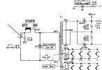
I need to add the .01uF cap on the power switch as shown in the attached picture. Does this need to be a "X"-type cap, or will just a standard 250v ceramic be safe? This amp has a mild pop when switched off - should this cap resolve that problem?
 

Attachments

  • PS-Cap.png
    PS-Cap.png
    230.1 KB · Views: 7
No X cap. Was this cap removed or missing, and you are replacing it, or adding it to match the schematic? If it was there, it was probably a regular ceramic with a 250V or greater rating.

If it were mine, I'd leave it out. It adds more danger than it remedies. I suspect this amp has only a two-prong, non-polarized cord right? As such, the transformer provides tremendous protection by electrically isolating the chassis from the line power. There is really little good reason to connect the chassis via a capacitor to either the neutral or hot side of the power line depending upon which way the plug is inserted into the outlet.

The pop is a different issue. To remedy this, connect a 0.01uF cap at 1000V or greater across the transformer primary. This will not only suppress the pop from the switch, but act to squelch RF noise coming in from the power line that can couple into the secondary side of the transformer.
 
Line to chassis is a Y type. Across the switch or across the line is an X type. Or just get XY types and they work for both. I'm not a huge fan of line to chassis caps
 
The cap was never there and wanted to add if it would suppress the pop. Yes, non-polarized 2-prong plug. Thanks for the information. I will add across the primary. Seems like in that application an X2 would be appropriate.
 
How does that upper output tube get any drive signal? Schematic error?

It's just drawn funny. The second half of the 6U8 tube V2B, is a "concertina", "split-load", or "cathodyne" phase splitter. The tube has a load resistor at the cathode of 39K to ground, and an identical load resistor at the plate of 39K to the 260V supply drawn at the bottom. One AC current flows through both, generating signals of opposite polarity to each output tube.


1764401797082.png
 
Cap should go across the switch or across the accessory outlet to suppress the pop (that all ASRs have), X or XY type preferred.
 
So, I read this suggestion sometime ago, after I had my 433 buttoned up and in place.

Rather than unhook everything and open it back up, I wired an XY cap to a non-polarized plug and plugged it into the accessory outlet.

Just presenting this for readers who might want to do this after the fact.
 
Back
Top Bottom