

You are using an out of date browser. It may not display this or other websites correctly.
You should upgrade or use an alternative browser.
You should upgrade or use an alternative browser.
stromberg carlson rp 721
- Thread starter churchill127
- Start date

churchill127
Member
Is that the GS changer that stops the platter, drops the record, then starts again? Thats a neat mechanism.
Just checked it out. The platter keeps spinning when changing records. It does have an arm mechanism that is pressed back by a 12 inch record when it drops, not sure if that will adjust speed or just signals whether there is a record or not. It works, but there is a steady audible beat made by some mechanism; I'm sure the entire turntable could use a good overhaul. Also doesn't seem like it does that well in a standard phono output, maybe because of the ceramic cartridge?? Could perhaps use a new cartridge.
looks like people sell vintage turntable plinth bases on ebay, I could pick one up and then it would be a complete turntable

ceramics degrade and the output drops. Usually the little rubber saddle thing that the needle lays against gets hard and it stops transmitting vibrations into the piezoelectric generator. They also need a very high input impedance to work into, something like 2M ohms. Thump is probably a flat spot on the idler, and it likely needs the usual clean and lube stuff. If it doesn't stop and drop its not a GS-77 though. I don't really know much of anything about G-S changers other than the 77 has a neat changing function.
churchill127
Member
input jacks to the selector. Output from the selector to the "top" of the volume pot, wiper of the volume pot to the grid of the 7199, which is what should have originally connected to the input jacks. "bottom" of the volume pot goes to ground. You could probably use a 100k-250k volume pot.
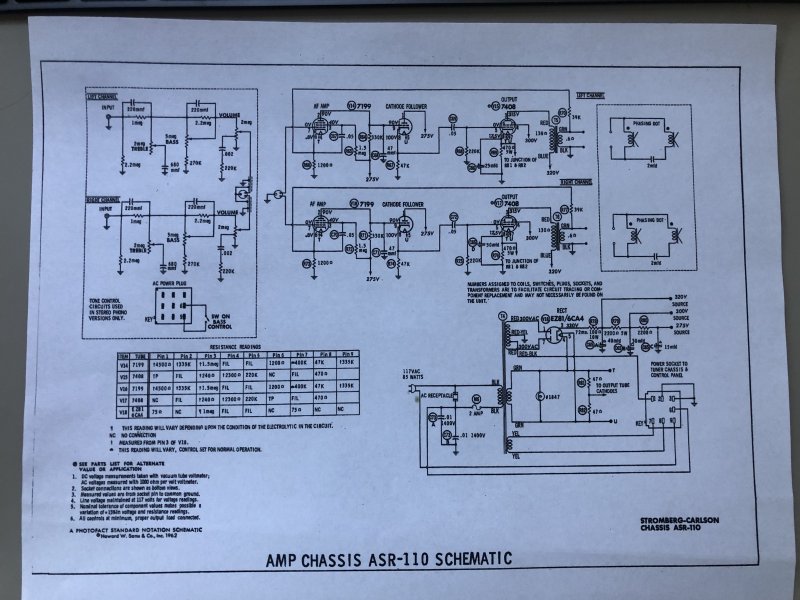
Thanks so much for all the advice! I am part way through my restoration/mod of the asr-110. I am somewhat confused by one section of the schematic that revolves around the can capacitor (65A-D). 65A-C seem to be running in series off of the rectifier tube, with the negatives going to ground. 65D however shows up with its positive connecting to one of the output tubes in parallel with resistor 76. So I am basically wondering if I can connect together the ground wires for capacitors 65A-D and connect them to ground together, and then connect their positives to all their individual places within the circuit, or whether I have to pay special attention to where I connect the ground of 65D.
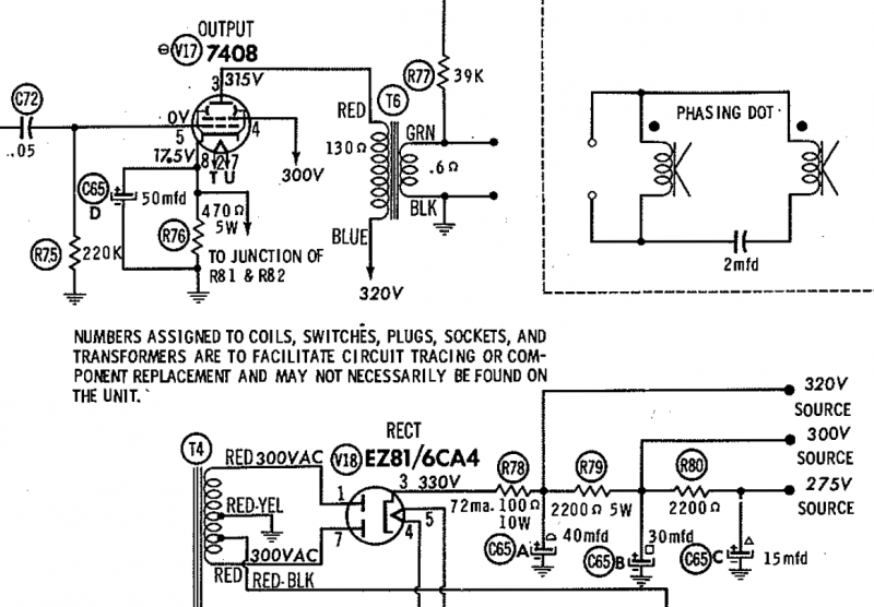
If anyone can shed some light on the matter, that would be awesome!
thanks!

century tek
Addicted Member
Yes, you can use one universal ground anywhere on the chassis but for noise or hum sake, it is best to have all your grounds at the center tap or close to it. Also make sure you keep those resistors at each positive point because they are the dropping resistors used for the different voltages through out the preamp circuitry.
"D" is the cathode bypass capacitor and you can use a separate capacitor there. This is usually one inside the can labeled as 50uF @ 25VDC.
EDIT: FYI, the can capacitor has four individual capacitors housed inside one unit. Inside, their negatives are connected together and connected to the outer can itself. The positives are the "A", "B", "C" and "D" designations on the schematic. Some people who replace these either like to replace the whole can while others will replace them with individual one's while others will stuff the old can and keep everything original looking.
"D" is the cathode bypass capacitor and you can use a separate capacitor there. This is usually one inside the can labeled as 50uF @ 25VDC.
EDIT: FYI, the can capacitor has four individual capacitors housed inside one unit. Inside, their negatives are connected together and connected to the outer can itself. The positives are the "A", "B", "C" and "D" designations on the schematic. Some people who replace these either like to replace the whole can while others will replace them with individual one's while others will stuff the old can and keep everything original looking.
Last edited:
churchill127
Member
Yes, you can use one universal ground anywhere on the chassis but for noise or hum sake, it is best to have all your grounds at the center tap or close to it. Also make sure you keep those resistors at each positive point because they are the dropping resistors used for the different voltages through out the preamp circuitry.
"D" is the cathode bypass capacitor and you can use a separate capacitor there. This is usually one inside the can labeled as 50uF @ 25VDC.
EDIT: FYI, the can capacitor has four individual capacitors housed inside one unit. Inside, their negatives are connected together and connected to the outer can itself. The positives are the "A", "B", "C" and "D" designations on the schematic. Some people who replace these either like to replace the whole can while others will replace them with individual one's while others will stuff the old can and keep everything original looking.
Thanks for the response! Ok, I decided to use 4 individual capacitors and ground all of them to the ground tab that was inside the can after I removed it. I am about 3/5ths of the way through a complete rewiring and recap of the amp, it has been alot of fun and a great learning experience. I really should have just ordered all the resistors and replaced those too, but all of them have spec'ed out to pretty close to their original values, so I am only planning on replacing a few of them. The plan is to make it into essentially a power amp, with a gain pot, and one output, and pair it with a solid state preamp (which I have yet to acquire because cheap ones are apparently quite rare!) I have a set of Zenith allegro 1000's which I believe should be efficient enough to work with this amp well, but I don't know if I want to take them away from the Zenith solid state console they are attached to. I hope to have it finished soon, will show more pics!
If anyone has recommendations for decent cheap preamps, I am all ears.
churchill127
Member
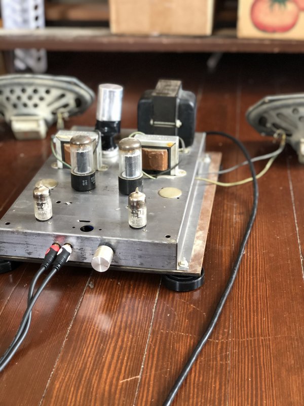
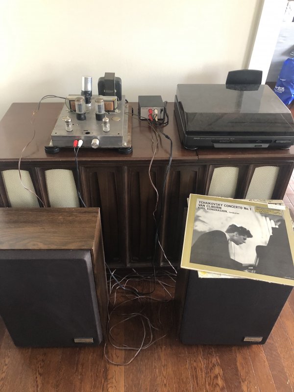
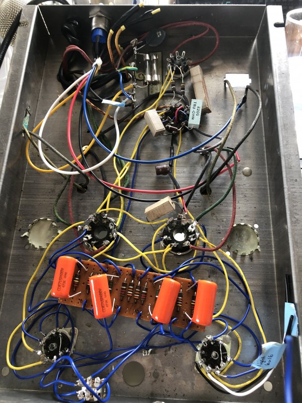
Update! I rewired every connection, replaced all electrolytic and ceramic capacitors, and added a 10k pot (I feel like it really needs a 100k though). The tubes the amp came with are producing sound, and it really sounds quite nice coming out of the zenith speakers. There is a decently loud noise floor, but that seems to go away when music is playing.
While testing it, there was some intermittent loud buzzing sounds which would occur with the volume pot turned completely down. I did not change much other than adding a grounded three prong ac cord which is separately grounded to chassis. There is one star ground where the can capacitor used to be, and another near the audio input. As it comes and goes, does it make sense that these loud noises might be due to a bad tube rather than a ground issue? Should I try new power tubes?
churchill127
Member
Sounds more like a loose connection. Might want to use a wood stick to poke around in there to see if anything shakes loose. Could also be dirty tube sockets if you haven't cleaned those.
Touching things with a plastic chopstick revealed a loose connection in the can capacitor section! Thanks for the tip. Now there are no weird noises, but there is an ever present high pitched hum that you that is a little bit louder than it should be I think. Do you think that would mean time for new tubes?
what frequency is the hum?
More likely either wire routing or a ground loop problem. Normally with a star ground you have one connection to chassis, not two. The flying wire leads might also be an issue. They appear to loop around in there a lot. If the have any power connections they need to be routed away from signal leads.
The leads coming out through holes in the chassis, are those the speaker connections? If the negative side of that isn't connected to chassis it won't behave itself properly either. The feedback system stops working without the transformer secondary grounded, and that can cause some strange behavior.
More likely either wire routing or a ground loop problem. Normally with a star ground you have one connection to chassis, not two. The flying wire leads might also be an issue. They appear to loop around in there a lot. If the have any power connections they need to be routed away from signal leads.
The leads coming out through holes in the chassis, are those the speaker connections? If the negative side of that isn't connected to chassis it won't behave itself properly either. The feedback system stops working without the transformer secondary grounded, and that can cause some strange behavior.
churchill127
Member
what frequency is the hum?
More likely either wire routing or a ground loop problem. Normally with a star ground you have one connection to chassis, not two. The flying wire leads might also be an issue. They appear to loop around in there a lot. If the have any power connections they need to be routed away from signal leads.
The leads coming out through holes in the chassis, are those the speaker connections? If the negative side of that isn't connected to chassis it won't behave itself properly either. The feedback system stops working without the transformer secondary grounded, and that can cause some strange behavior.
Thanks for all the advice gadget! I don't have an oscilloscope, so not sure how I could measure the frequency of the hum; I will try and record it and see if I can find out that way.
The connections to chassis are the original way it was laid out, I could try and find a way to simplify it, perhaps by running a bus wire from the star ground to the input area?
As for the flying wires... yea it was my first attempt at restoring a tube amp with point to point wiring, so I definitely could have gotten it a little bit tighter; I think that I will eventually overhaul this whole thing once I get a proper wire stripper.
The speaker leads are the original leads coming out of the transformer secondary, and they were originally connected straight to the speakers. I am planning on drilling holes in the chassis for speaker posts, so I will ground the negative lead. So best practice would be to ground this back to the star ground?
smartphone and an instrument tuner app might get it done. There's an app for everything, I'd be surprised if something of that nature didn't exist.
Failing all else, touch the input wire with your finger while the volume is up some. That will be 60. If the hum you normally get is higher pitch you probably have 120 which means power supply filtering. 60 will be ground loop, wire routing, or possibly leaky heater-cathode insulation in one of the tubes.
try and tuck the new wiring to the edges of the chassis, especially anything that connects to the 120v power feeds. Twist the leads too if at all possible, it helps cancel hum fields.
If the leads are how they originally were, it ought to have been grounded already but not exactly sure how. Never worked on this model so the physical details a If the wires come right out of the transformer and don't go anywhere else I don't see how that was done. There should be a connection to the + side as well for the feedback circuit. Schematic shows a 39k resistor ties to the + speaker lead, so that would be your feedback connection. Normally the output transformer leads go to a terminal strip or something where other things are connected, and then out to the speakers. You may have to trace things out a bit to see if or where that 39k resistor is.
Failing all else, touch the input wire with your finger while the volume is up some. That will be 60. If the hum you normally get is higher pitch you probably have 120 which means power supply filtering. 60 will be ground loop, wire routing, or possibly leaky heater-cathode insulation in one of the tubes.
try and tuck the new wiring to the edges of the chassis, especially anything that connects to the 120v power feeds. Twist the leads too if at all possible, it helps cancel hum fields.
If the leads are how they originally were, it ought to have been grounded already but not exactly sure how. Never worked on this model so the physical details a If the wires come right out of the transformer and don't go anywhere else I don't see how that was done. There should be a connection to the + side as well for the feedback circuit. Schematic shows a 39k resistor ties to the + speaker lead, so that would be your feedback connection. Normally the output transformer leads go to a terminal strip or something where other things are connected, and then out to the speakers. You may have to trace things out a bit to see if or where that 39k resistor is.
churchill127
Member
smartphone and an instrument tuner app might get it done. There's an app for everything, I'd be surprised if something of that nature didn't exist.
Failing all else, touch the input wire with your finger while the volume is up some. That will be 60. If the hum you normally get is higher pitch you probably have 120 which means power supply filtering. 60 will be ground loop, wire routing, or possibly leaky heater-cathode insulation in one of the tubes.
try and tuck the new wiring to the edges of the chassis, especially anything that connects to the 120v power feeds. Twist the leads too if at all possible, it helps cancel hum fields.
If the leads are how they originally were, it ought to have been grounded already but not exactly sure how. Never worked on this model so the physical details a If the wires come right out of the transformer and don't go anywhere else I don't see how that was done. There should be a connection to the + side as well for the feedback circuit. Schematic shows a 39k resistor ties to the + speaker lead, so that would be your feedback connection. Normally the output transformer leads go to a terminal strip or something where other things are connected, and then out to the speakers. You may have to trace things out a bit to see if or where that 39k resistor is.
As always, thank you Gadget for the helpful comments. I decided to try another audio source to make sure it wasnt coming upstream of the amp, and was able to track it back to the realistic phono preamp I am using or the turntable itself (but that seems far less likely). Hooked up a bluetooth receiver and it was whisper silent and during playback sounded great. At some point I will need to hunt down that loose connection and drill holes for proper speaker mounts, but I'm enjoying the feeling of accomplishment right now.
This amp sounds great coming out of the allegro 1000's! My end goal is to slap some boards into the old cabinet of the console it came out of, and fashion it into a record cabinet where the old speakers used to be, and have the amp and a turntable on top, perhaps with the speakers too if they will fit.
I just became the owner of a broken old kenwood kd-5033af, so that will be the next step towards making a little vintage hi-fi corner. Again, thanks so much for all the advice! It really helped.