• The move to the new server is done. There are some software and database maintenance updates in process. This has us passing the hat around to help out. We appreciate any donations. Seriously, even a dollar helps. The payment page may be found here - https://www.audiokarma.org/support.html

STVs and heatsink compound Question

merlynski

Curmudgeon Electronicist
I am in the middle of rebuilding the power amp in my SX-1050 and I added some heatsink compound between the STV and the heatsinks for the drivers. I will do so on the main heatsink STVs as well. I have not seen it mentioned in any threads, though I think I have seen a few times it was done in posted pics. Has anybody done it themselves? Any difference, good or bad? Has anybody seen it from an OEM?
 
Register to hide this ad
IMO, the compound facilitates the transfer of heat to the STV.
so as to make it more responsive to heatsink temperature rise, and have less thermal lag for bias control. The STV bias control is a thermally coupled servo, with the STV being the negative feedback sensor for the bias circuit. Or I may be overthinking it, wouldn't be the first time :rolleyes:.

But, that is why I asked the question . . .
 
Have seen heatsink compound used for the bias components from the factory; sometimes the compound is clear rather than white, so not as obvious.
Yamaha does it all the time.. :thumbsup:
not trying to dissipate so the simple clamped-contact is adequate
Oh contraire.. You are dissipating heat from the sink to the device.Well not dissipating but transferring..:biggrin:
 
Last edited:
When you model the difference in thermal resistance (goop vs dry) versus the heat flow THROUGH the thermal diode case to the environment (EVERYTHING is a heat radiator to some degree) you will find the difference is swamped out by other parameters. Long long ago I had to wrap my mind around all that. I would have (almost) KILLED to have the FLIR imaging capability that is available nowadays.

The diode actually INSULATES that area of the heat sink a bit - impeding the flow of heat out. And that implies a slightly greater temperature at the diode case.
 
Either it was not significant enough or it was not desired by Pioneer Engineers or they would have applied the paste that they obviously had on-hand when building your amplifier and the many thousands of others, and many different designs that were produced without the thermal paste.

It can be argued that this could increase the response time somewhat, or could reduce by some small amount the temperature differential between the heatsinks and STVs, but it is painfully obvious to me that through extensive engineering and testing it was designed and built to be a clean-dry junction.

Thermal compound is great for ensuring the most coupling so that a device can dissipate as much heat as possible, certainly great to keep a power transistor running as cool as possible. I believe that the amount of contact surface that the STV has in contact with the heatsink is more than enough for it to perform its function or again, it would have been pasted. Completely different application and the circuit is designed to be coupled as-is (and I agree with Mark that this is far from the biggest lag in this circuit).
 
The heatsink has a high thermal capacity, so it will not change temperature fast enough to require rapid heat transfer to the STV. Thermal compound should not make any significant difference. Having said that, adding thermal compound to the STV-heatsink interface should not hurt anything. Just make sure that it is not the kind used for computer CPUs, which can be electrically conductive.

Enjoy,
Rich P
 
Adding some thermal compound is not going to make a whole lot of different in this configuration. The compound can be electrical conductive since the package is insulated/isolated.
More importantly is where the bias Gen thermal sensor is placed. Pioneer’s method is less than optimal due to very long response lag due to thermal inertia of a large heatsink. The best place to sense temp is on the die or right at one of the o/p device packages. We found that using a metal tab packaged device as the sensor (Mje15032) sitting on top of the o/p device offered better performance vs an isolated package like a To-126. Using a to-3 package does not make doing so very easy compared to plastic packaged devices.
 
Adding some thermal compound is not going to make a whole lot of different in this configuration. The compound can be electrical conductive since the package is insulated/isolated.
More importantly is where the bias Gen thermal sensor is placed. Pioneer’s method is less than optimal due to very long response lag due to thermal inertia of a large heatsink. The best place to sense temp is on the die or right at one of the o/p device packages. We found that using a metal tab packaged device as the sensor (Mje15032) sitting on top of the o/p device offered better performance vs an isolated package like a To-126. Using a to-3 package does not make doing so very easy compared to plastic packaged devices.
Were you using the MJE15032 as the active device in a Vbe multiplier configuration?
 
Last edited:
Yes that it what Bob Cordell decided to use, it did not have to be that particular device, the essence was the package type mounted right on top of one of the OPS bjts, (MJL1381 or MJL1302) vs the device type for which many types qualify. The bigger die in the MJE15032 does help too. In the 1st rev we used a KSC3503, but it was not responsive enough, found a better solution.
Q14,15,16 get mounted to a small HS on the driver board and Q13 gets mounted to the OPS. It works really well, almost as good as a die sensing NJL1381/1302 ThermalTrak types.
 

Attachments

Last edited:
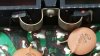
The two compensating components on this Luxman R1120 are KSC1845's. I can't remember what the originals were but I suspected this arrangement was the demise of this particular amp.
The amp board warped bringing the compensating devices out of the heatsink valley.
Luxman located them in the heatsink cavity with no type of fastening. The fiber foam material is my idea. No scientific data, only that it's been working for several years without issues.
The right amp was mostly blown out. The most damaged amp I've had to date. You can see remnants of the damage on the ceramic cap.

index.php
 
Back
Top Bottom