• The move to the new server is done. There are some software and database maintenance updates in process. This has us passing the hat around to help out. We appreciate any donations. Seriously, even a dollar helps. The payment page may be found here - https://www.audiokarma.org/support.html

SX-1000TD Odd problem - hoping for some help

Nothing remarkable about measurements of the tone pots.

The balance pot seems to give an odd reading. When centered, and measuring from wiper to one end, the left gang reads 28.9 ohms. The right reads 3.2 ohms.

When knob is turned full left, both gangs measure same (.7 ohms). When turned full left, they are close (28.9 vs 26.8).

This pot is fully connected, so I guess there could be interference from other components. And, honestly, I'm not sure what to expect with a balance pot. I would have guessed that turned fully one way, I should see low resistance on one channel and high on the other.
 
Lets try something. Switch the Left channel pin 2 wire and the Right channel pin 2 wire at the W15-031 board (outputs), then listen to hear if the weak bass switches channels or not. If it does the problem is before the pin 2 connections, if it does not, the problem is after the W15-031 board. That is a much simpler option than anything else I can come up with. And it is easily done since the wires are soldered to the board, rather than wire wrapped.


I did that quite a while back. It switched...which takes us back to the balance pot, then the low filter, then back to the tone (control) board.
 
I did that quite a while back. It switched...which takes us back to the balance pot, then the low filter, then back to the tone (control) board.
Was that the wire to the Main amp inputs (at pin 2) you switched before? I am referring to the output wire of the control amp at the control amp, which is labeled as pin 2 on the W15-031 schematic. Swap the wires on output pin 2 of the W15-031, which is before the balance pot.
This is the similar to what you did before, but further upstream in the signal path. If it changes sides the problem is occurring before the balance pot.

The balance pot has one end connected to ground, one end connected to the output of the control amp, which has a 47kΩ resistor to ground (on the schematic I have from your post). That parallel resistance will alter how the wiper resistance changes as it is turned, and the resistance across it. The balance pot has an (HB) after the value on the schematic, which makes me think it is not a linear resistance change as it rotates. An (A) type pot has an 'Audio' taper, a (B) type pot is linear. I have not found an explanation of what (HB) means yet.
 
Last edited:
Using signal tracer at #10 terminals of the tone board (input from the volume control), both channels sound the same, and loudness and bass tone control affect both channels equally. All good here, it seems.

At #2 terminals (output to the low filter, which then goes to balance pot, and onward to the notch filter and power amp), the problem is evident. So it seems clear that the issue is somewhere on the tone board itself, right?

EDIT I can certainly swap the terminal 2 wiring, but doesn't the above confirm it is before both the balance pot and low filter (and after the preamp, volume control and loudness switch)?
 
Succinct description of symptoms:
  • R slightly lower volume than L
  • Effect of loudness function and bass tone control notably less on R than L
 
Using signal tracer at #10 terminals of the tone board (input from the volume control), both channels sound the same, and loudness and bass tone control affect both channels equally. All good here, it seems.

At #2 terminals (output to the low filter, which then goes to balance pot, and onward to the notch filter and power amp), the problem is evident. So it seems clear that the issue is somewhere on the tone board itself, right?

EDIT I can certainly swap the terminal 2 wiring, but doesn't the above confirm it is before both the balance pot and low filter (and after the preamp, volume control and loudness switch)?

It does seem clear, but that is a logical conclusion, where actually moving the wires provides positive proof. We have not found any component failures or open traces on the W15-031 yet, so it needs experimentation. It could be a problem with the balance circuit loading the output of the W15-031, rather than a failure on the board. When you take a measurement you have to remember you are looking at a point in a circuit that is affected by both sides around the test point, upstream and downstream. Moving the wires actually separates the sections in the signal path.
 
Have to admit that I now question the usefulness of the signal tracer. If the problem can still be either upstream or downstream of the point at which symptom occurs, how does it help?

In any case, I will get the outputs from the tone board swapped and tested later this morning.
 
The point tested is connected to the components all around it, but different circuits, by intention and/or function, isolate stages in the signal path from each other. The signal tracer is like a window, the signal it picks up is affected by components before and after (all around) that point, but the circuit design and signal flow define the edges of the window. Sometimes caps are used to pass signal, but block DC, like coupling caps in the signal path. Some are designed to pass DC but eliminate AC, like power supplies, ripple killers, and power supply decoupling circuits. Sometimes an amplifier stage is deliberately designed to block component effects after it from affecting the signal before it. Sometimes a specific frequency range is passed upstream as feedback to affect the signal coming into a stage, like in a tone control stage. Sometimes feedback is used to control gain, or diminish distortion. You have to look at the circuit, and understand how it works to see where and how the signal is passed, blocked, or fed back, or fed forward. It is a constant learning process, for all of us. You are thinking of good questions, and moving along the right path to learn circuit function and troubleshooting. You just need more 'book learning' about electronics, and more experience troubleshooting. Don't get discouraged, electronics is hard because you cannot see how it works, like when you are looking at a mechanical device. upload_2021-3-6_9-12-44.gif

EDIT: more
 
Last edited:
Swapped them.

Bizarrely, both channels seem to be working fine...equal output, tone controls and loudness have equal effect. Let it run 30 minutes, since problem sometimes takes 10-15 minutes to occur.

Swapped them back, both channels pretty close to equal. Right still very slightly lower, but effect of loudness and tone control seems almost equal.

I can't even make a guess on what the underlying issue is (or was, assuming it keeps working as it is now). If it stays like this, I think the variance between the channels is small enough to be acceptable.
 
Will move on to replacing filter and speaker coupling caps.

On that note; unit was built such that resistors are soldered directly to capacitor solder tabs, and wiring to caps is tight...no slack. I plan to solder "extension" wires to the resistors and exiting wiring to make installation easier. See any issues with doing this?

Alternatively, I've read that another approach in such situations is to cut the tabs of the existing caps (leaving all their connections in place) and then solder them to the tabs of the new caps. Getting a clipper in place to do this may not be possible, but if it is, seems like it could be a good idea. Any comments on this approach?

Thanks!
 
Last edited:
Swapped them.

Bizarrely, both channels seem to be working fine...equal output, tone controls and loudness have equal effect. Let it run 30 minutes, since problem sometimes takes 10-15 minutes to occur.

Swapped them back, both channels pretty close to equal. Right still very slightly lower, but effect of loudness and tone control seems almost equal.

I can't even make a guess on what the underlying issue is (or was, assuming it keeps working as it is now). If it stays like this, I think the variance between the channels is small enough to be acceptable.
Excellent!
I now suspect that there was a cold solder joint on the wire connection of the right channel output of the W15-031. Unsoldering and resoldering made a good connection. That 'explanation' fits with not being able to find a problem on the board itself, or on the balance pot. The other possible action is to reflow every solder joint on the board, if that has not been done already.

Will move on to replacing filter and speaker coupling caps.

On that note; unit was built such that resistors are soldered directly to capacitor solder tabs, and wiring to caps is tight...no slack. I plan to solder "extension" wires to the resistors and exiting wiring to make installation easier. See any issues with doing this?

Alternatively, I've read that an alternative is to cut off the tabs of the existing caps (leaving all their connections in place) and then solder them to the tabs of the new caps. Getting a clipper in place to do this may not be possible, but if it is, seems like it could be a good idea. Any comments on this approach?

Thanks!
I would do whatever seems easiest, and less likely to damage anything that you want to keep. Since I can't really see it, I don't have another opinion.
If you can work a little slack out of the wiring harness that would be good.

EDIT: more
 
Last edited:
Damn, damn, damn....after running for another 25 mins, output difference in right channel is becoming more noticeable again.

BTW, this is true even when I switch the mode selector to right channel only, left channel only, or stereo.

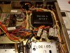
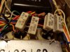
As regards the big caps....pics for your viewing pleasure:

20210306_122637.jpg
20210306_122632.jpg
20210306_122557.jpg
 
Alternatively, I've read that another approach in such situations is to cut the tabs of the existing caps (leaving all their connections in place) and then solder them to the tabs of the new caps. Getting a clipper in place to do this may not be possible, but if it is, seems like it could be a good idea

I like that idea, I might try it if I replace my coupling caps on my 395. I would try loosening the cap from the clamp first so as to have a little wiggle room getting the clippers in place.
 
Ok, that stinks, did you reflow all the solder joints on the W15-031?
Try switching the pin 2 outputs again, and play it till it warms up good, then listen.
I am starting to believe it is a component failing as it warms up, rather than a constant failure.
Or possibly a very fine line crack in a trace that opens up as it warms.
The description points at a week feed forward signal on the bass side of the tone control circuit on the W15-031, between the pin 6 node and the base of Q603 node

EDIT: more
 
Last edited:
Did not reflow all joints...the only thing left are the resistors and some of the terminals. Everything else on board is new.

Swapped terminal 2 again...problem went with the channel this time. Swapped back, problem stays with R channel, as expected.

Unit has been on all day. Will reflow remaining joints tonite.

If it helps, the problem is evident at both the treble and bass pots, which I don't think I had tested previously.

Also evident at the high filter.
 
Last edited:
B, C and E voltages are very close on both sets of transistors (comparing R to L).
You are getting the process down now!

So it changes with the swap, that means the failure is before the output pin 2.
Is it evident on R channel input pin 10? The Q602 gain stage should keep it from showing up there if the cause is after Q602. Try switching the input pin 10 wires and see if it switches channels or not.
 
Do you have any freeze spray? You could try a quick spritz on the resistors, 1 at a time, that have not been changed and see if the problem goes away.
 
Back
Top Bottom