• The move to the new server is done. There are some software and database maintenance updates in process. This has us passing the hat around to help out. We appreciate any donations. Seriously, even a dollar helps. The payment page may be found here - https://www.audiokarma.org/support.html

tutor_turtle

AK Subscriber
Subscriber
After Recapping every board except the driver boards, everything checked out.
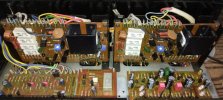
WhenI got to the first driver board, I discovered it had warped due to excessive heat.
When I started replacing parts, traces fractured left and right.
I got to the point of having to pull the board completely out of the chassis to rework it properly, replacing every fractured trace.
After triple checking I had all the correct transistors in their proper locations, I brought it up slowly using a variac.
The bias is going over 1 volt before even getting the 10% of line voltage. Varying the bias pot has no effect.
I read on one of the old posts I could remove the output transistors and put a resistor across collector - emitter to trouble shoot without worry of blowing the hard-to-find original outputs.
What value should I use?
 
Register to hide this ad
1K ohm
You probably still have and open trace in the bias/idle circuit.
I may have a good board you can have.
Its the circuit between the collectors of Q4 and Q5, including to the drivers base of Q7 and Q8.
Make sure the STV diode is secure and the hair wires are in good contact with the board.
 
Last edited:
Hi guys,
Going a bit off topic here
I have only worked on one sx-1010 and do not own one. My question is, do both versions of sx-1010 using awh-032 amp boards -0, -D? have a place on the big heatsink to mount the STV diode stack?
I have been asked to reproduce a awh-032 but it’s a tougher nut to crack mechanically because of the wire wrap posts. Does one just duplicate the pcb as is or does one attempt a different connection arrangement? Either way it’s still a PITA to transfer wires/terminals over to a new pcb. Thanks
 
I don’t remember about the heatsink mounting.
Do you need a board for evaluation?
The posts are the “F” style, difficult to remove without damaging the board. If a guy wanted to use the post on/in the terminal?
The terminals would work. The output harness would have enough service lead left to make a terminal connection.
 
Hi guys,
Going a bit off topic here
I have only worked on one sx-1010 and do not own one. My question is, do both versions of sx-1010 using awh-032 amp boards -0, -D? have a place on the big heatsink to mount the STV diode stack?
I have been asked to reproduce a awh-032 but it’s a tougher nut to crack mechanically because of the wire wrap posts. Does one just duplicate the pcb as is or does one attempt a different connection arrangement? Either way it’s still a PITA to transfer wires/terminals over to a new pcb. Thanks
mine is uses "-d". you can see the stvs so hope it helps.

moar sx 041.jpg

find someone that has "-o" and you will have your answer.....i think

Does one just duplicate the pcb as is or does one attempt a different connection arrangement?

i don't see any reason to stray very far from original. like you said, it's a pita no matter what. the top row could be screw connectors for bare wire but you have limited access to use them for the lower wires. molex type connectors would be excellent in those locations but then you would need to supply pigtails because not alot of people have the proper crimpers to repin molex. (i don't)

actually, i don't think molex would work on the bottom. might not be enough clearance thru the chassis
moar sx 008.jpg


hope my reply is in line with what you are asking.
 
1K ohm
You probably still have and open trace in the bias/idle circuit.
I may have a good board you can have.
Its the circuit between the collectors of Q4 and Q5, including to the drivers base of Q7 and Q8.
Make sure the STV diode is secure and the hair wires are in good contact with the board.
I would sure appreciate any help you can give me zeb.
Input of Q4,5 Look ok, maybe a little high +&- 2v. The output is pegged at +55V.
D4,5 test good on a transistor checker, wires look good.
And I have one spare from a Rev D board.
The problem is, I fix one trace and I break two more.
This board (right channel) is in bad shape, while the left looks fine.
I've not sent a PM before. How does it work?
 
Do you need a board for evaluation?
That would be very kind of you for me to measure it up and return it to you ASAP. Sounds like many awh-032 are in rough shape and fragile to repair after years of use. Even though it’s a lot of work to remove the wires from the wrap posts and re-install into screw down terminal, it’s the best way to do it esp if one wants to sell a new assembled and tested unit.

Thanks for the pics to add to my collection. I have seen pics on the web to reference as well

On the PM question, there is a envelope icon on the top to use. “Start a new conversation”
Back to the thread at hand
 
Last edited:
Hi guys,
Going a bit off topic here
I have only worked on one sx-1010 and do not own one. My question is, do both versions of sx-1010 using awh-032 amp boards -0, -D? have a place on the big heatsink to mount the STV diode stack?
I have been asked to reproduce a awh-032 but it’s a tougher nut to crack mechanically because of the wire wrap posts. Does one just duplicate the pcb as is or does one attempt a different connection arrangement? Either way it’s still a PITA to transfer wires/terminals over to a new pcb. Thanks
I would be the person requisitioning your services. :cool:
Yes. Both versions have the big heat sink.
Version D, runs jumper wires from D6 to two extra (unlabeled) pins, located between pins 17 & 18.
Version O maintains D6 next to Q10.
I would stick the the screw terminal solution, at least on the top
The bottom could get attached first, possibly requiring a small extension of the leads.
The Signal input on pins 5 & 6 might be a little tricky maintaining a noise-free path. (A twisted pair?)
I would jump pins 3 & 7 (-56v) on the board, eliminating the need for the existing external jumper (Orange: left channel, & Orange w/white trace: right)
The other approach could be 6 slightly over-sized solder pads.
Do they make little push-button terminals?
 
That would be very kind of you for me to measure it up and return it to you ASAP.

Thanks for the pics to add to my collection.

On the PM question, there is a envelope icon on the top to use. “Start a new conversation”
Thank you kindly.
 
Okay thanks for your suggestions.

Yes they make push button terminal blocks as well. Do not grab the wires as well imo.
Still have an issue of being able to release the wires too. Short shaft screw driver either way. I think the screw down terminal blocks can be made to work or use the holes for them to solder wires directly although getting a soldering iron in there for the bottom is no easy task.
Okay I’ll commit to doing the new design, but it will take some time, 2025 for sure, when exactly, not so sure. Basically a new layout for the awh-048 that was done previously, so most of the work can be re-used.
 
Last edited:
Check the traces running along the bottom of the board. They break from flexing and mounting, unmounting.
 
Hi guys,
Going a bit off topic here
I have only worked on one sx-1010 and do not own one. My question is, do both versions of sx-1010 using awh-032 amp boards -0, -D? have a place on the big heatsink to mount the STV diode stack?
I have been asked to reproduce a awh-032 but it’s a tougher nut to crack mechanically because of the wire wrap posts. Does one just duplicate the pcb as is or does one attempt a different connection arrangement? Either way it’s still a PITA to transfer wires/terminals over to a new pcb. Thanks
I really, really dislike the screw terminal connectors. They just look clunky and hokey. When I've used your power supply boards in the past, I transferred the wire wrap posts to the new board.
Here's what I did with a Marantz 300DC, all new Molex connectors. The crimpers aren't terribly expensive on the 'bay.
index.php


index.php


Thread: https://audiokarma.org/forums/index.php?threads/marantz-300dc-basket-case.1082033/
 
I really, really dislike the screw terminal connectors. They just look clunky and hokey. When I've used your power supply boards in the past, I transferred the wire wrap posts to the new board.
Here's what I did with a Marantz 300DC, all new Molex connectors. The crimpers aren't terribly expensive on the 'bay.
index.php


index.php


Thread: https://audiokarma.org/forums/index.php?threads/marantz-300dc-basket-case.1082033/
Coming from 35 years as a DoD civilian contractor, we designed in lots of Molex.
I sure wish I had my old tool box from work
 
Check the traces running along the bottom of the board. They break from flexing and mounting, unmounting.
So this is where I've arrived at: Q4. The collector should be 1.8V it is 56.8V.
Emitter: 58.9V, Base: 57.2V. 1.7volts shouldn't turn that device fully on?
This runs through there bias adjuster VR2, > two STV thermal diodes D5,6 > to the complementary collector of Q5, where it should measure -1.8V. but measures +36V

The kit I bought from Ben says Q4 (2SB528) could be a KSA1220 or TTA004, I used a KSA part.
Q5 (2SC1451) could be TTC004 or KSC2690, again I used the KSC part. I've had good luck with On-Semi.

I could swap out Q4, but think I'm missing something here.
The board is so fragile, I hate to rework it more than I absolutely need to.
 
.6v is turn-on.
KSA is a PNP which is what's needed.
Is Q4 shorted?

Courtesy MTF cira 2023:
Lots of those transistors on the old lists are going end of life, so there are changes:

replacement parts for SX-1010 power amplifier awh-032 (for one channel - double up to do both)
sx-1010 AWH032 amplifier board x 2 boards
Q1 Q2 Q3 2sa726 to-92 bce : 512-KSA992FBta (ln)to-92 ecb 120v .05a .5w 100mhz 150-800hfe $0.05 ea
Q4 2sb528 to-202? bce : 512-KSA1381estu to-126 ecb 300v .1a 1.2/7w 150mhz 40-320hfe $0.53 ea
Q5 Q6 2sc1451 to-39 npn ebc : 512-KSC3503dstu to-126 ecb 300v .1a 1.2/7w 150mhz 40-320hfe $0.46 ea


Q7 2sd358 to-202? bce : 512-KSC3503dstu to-126 ecb 300v .1a 1.2/7w 150mhz 40-320hfe $0.46 ea
Q8 2sb528 to-202? bce : 512-KSA1381estu to-126 ecb 300v .1a 1.2/7w 150mhz 40-320hfe $0.53 ea
Q9 2sc1448 to-220 bce P: 512-KSC2073TU npn to-220 bce 150v 1.5a 25w 4mhz 40-140hfe $0.54
Q10 2sa740 to-220 bce : 512-KSA940TU_Q pnp to-220 bce 150v 1.5a 25w 4mhz 40-140hfe $0.54
Q11 2sc945 to-92 ecb : 512-KSC1845EBU (ln)to-92 ecb 120v .05a .5w 100mhz 150-800hfe $0.05 ea
Q12 2sa733 to-92 ecb : 512-KSA992FBU (ln)to-92 ecb 120v .05a .5w 100mhz 150-800hfe $0.05 ea


512-KSA992fta F 300-600 (ln)to-92 ecb 120v .05a .5w 100mhz 300-600hfe $0.39 ea
512-KSA992fbu F 300-600 (ln)to-92 ecb 120v .05a .5w 100mhz 300-600hfe $0.37 ea
512-KSA992fata FA 300-470 (ln)to-92 ecb 120v .05a .5w 100mhz 300-600hfe $0.38 ea
512-KSA992fbta FB 430-600 (ln)to-92 ecb 120v .05a .5w 100mhz 300-600hfe $0.32 ea
512-KSC1845Fta F 300-600 (ln)to-92 ecb 120v .05a .5w 100mhz 300-600hfe $0.05 ea
P 200-400 F 300-600 FA 300-470 FB 430-600 E 400-800 U 600-1200


512-KSA1381estu to-126 ecb 300v .1a 1.2/7w 150mhz 40-320hfe $0.53 ea
512-KSC3503dstu to-126 ecb 300v .1a 1.2/7w 150mhz 40-320hfe $0.46 ea


512-KSA940TU pnp to-220 bce 150v 1.5a 25w 4mhz 40-140hfe $0.62
512-KSC2073TU npn to-220 bce 150v 1.5a 25w 4mhz 40-140hfe $0.66
 
.6v is turn-on.
KSA is a PNP which is what's needed.
Is Q4 shorted?

Courtesy MTF cira 2023:
Lots of those transistors on the old lists are going end of life, so there are changes:

replacement parts for SX-1010 power amplifier awh-032 (for one channel - double up to do both)
sx-1010 AWH032 amplifier board x 2 boards
Q1 Q2 Q3 2sa726 to-92 bce : 512-KSA992FBta (ln)to-92 ecb 120v .05a .5w 100mhz 150-800hfe $0.05 ea
Q4 2sb528 to-202? bce : 512-KSA1381estu to-126 ecb 300v .1a 1.2/7w 150mhz 40-320hfe $0.53 ea
Q5 Q6 2sc1451 to-39 npn ebc : 512-KSC3503dstu to-126 ecb 300v .1a 1.2/7w 150mhz 40-320hfe $0.46 ea


Q7 2sd358 to-202? bce : 512-KSC3503dstu to-126 ecb 300v .1a 1.2/7w 150mhz 40-320hfe $0.46 ea
Q8 2sb528 to-202? bce : 512-KSA1381estu to-126 ecb 300v .1a 1.2/7w 150mhz 40-320hfe $0.53 ea
Q9 2sc1448 to-220 bce P: 512-KSC2073TU npn to-220 bce 150v 1.5a 25w 4mhz 40-140hfe $0.54
Q10 2sa740 to-220 bce : 512-KSA940TU_Q pnp to-220 bce 150v 1.5a 25w 4mhz 40-140hfe $0.54
Q11 2sc945 to-92 ecb : 512-KSC1845EBU (ln)to-92 ecb 120v .05a .5w 100mhz 150-800hfe $0.05 ea
Q12 2sa733 to-92 ecb : 512-KSA992FBU (ln)to-92 ecb 120v .05a .5w 100mhz 150-800hfe $0.05 ea


512-KSA992fta F 300-600 (ln)to-92 ecb 120v .05a .5w 100mhz 300-600hfe $0.39 ea
512-KSA992fbu F 300-600 (ln)to-92 ecb 120v .05a .5w 100mhz 300-600hfe $0.37 ea
512-KSA992fata FA 300-470 (ln)to-92 ecb 120v .05a .5w 100mhz 300-600hfe $0.38 ea
512-KSA992fbta FB 430-600 (ln)to-92 ecb 120v .05a .5w 100mhz 300-600hfe $0.32 ea
512-KSC1845Fta F 300-600 (ln)to-92 ecb 120v .05a .5w 100mhz 300-600hfe $0.05 ea
P 200-400 F 300-600 FA 300-470 FB 430-600 E 400-800 U 600-1200


512-KSA1381estu to-126 ecb 300v .1a 1.2/7w 150mhz 40-320hfe $0.53 ea
512-KSC3503dstu to-126 ecb 300v .1a 1.2/7w 150mhz 40-320hfe $0.46 ea


512-KSA940TU pnp to-220 bce 150v 1.5a 25w 4mhz 40-140hfe $0.62
512-KSC2073TU npn to-220 bce 150v 1.5a 25w 4mhz 40-140hfe $0.66
Q4 tests OK with Fluke meter on diode setting.

Q4,8 is KSA1220A-Y (TTA004B came with Ben's kit, is that part ok?)
For Q1,2,3, & 12 I used KSA992-F no other markings on the device.
Q5,6,7 is a KSC3503-D (TTC004B came with Ben's kit)
Q9 and10 were not replaced, but I do have KSC940T and KSA940T. Should I replace them?
For Q11 there is a KSC1845-F not an "E" type.

With the KSA992: what is the difference between the fta & the fbu extension?
 
Last edited:
.6v is turn-on.
KSA is a PNP which is what's needed.
Is Q4 shorted?

Courtesy MTF cira 2023:
Lots of those transistors on the old lists are going end of life, so there are changes:

replacement parts for SX-1010 power amplifier awh-032 (for one channel - double up to do both)
sx-1010 AWH032 amplifier board x 2 boards
Q1 Q2 Q3 2sa726 to-92 bce : 512-KSA992FBta (ln)to-92 ecb 120v .05a .5w 100mhz 150-800hfe $0.05 ea
Q4 2sb528 to-202? bce : 512-KSA1381estu to-126 ecb 300v .1a 1.2/7w 150mhz 40-320hfe $0.53 ea
Q5 Q6 2sc1451 to-39 npn ebc : 512-KSC3503dstu to-126 ecb 300v .1a 1.2/7w 150mhz 40-320hfe $0.46 ea


Q7 2sd358 to-202? bce : 512-KSC3503dstu to-126 ecb 300v .1a 1.2/7w 150mhz 40-320hfe $0.46 ea
Q8 2sb528 to-202? bce : 512-KSA1381estu to-126 ecb 300v .1a 1.2/7w 150mhz 40-320hfe $0.53 ea
Q9 2sc1448 to-220 bce P: 512-KSC2073TU npn to-220 bce 150v 1.5a 25w 4mhz 40-140hfe $0.54
Q10 2sa740 to-220 bce : 512-KSA940TU_Q pnp to-220 bce 150v 1.5a 25w 4mhz 40-140hfe $0.54
Q11 2sc945 to-92 ecb : 512-KSC1845EBU (ln)to-92 ecb 120v .05a .5w 100mhz 150-800hfe $0.05 ea
Q12 2sa733 to-92 ecb : 512-KSA992FBU (ln)to-92 ecb 120v .05a .5w 100mhz 150-800hfe $0.05 ea


512-KSA992fta F 300-600 (ln)to-92 ecb 120v .05a .5w 100mhz 300-600hfe $0.39 ea
512-KSA992fbu F 300-600 (ln)to-92 ecb 120v .05a .5w 100mhz 300-600hfe $0.37 ea
512-KSA992fata FA 300-470 (ln)to-92 ecb 120v .05a .5w 100mhz 300-600hfe $0.38 ea
512-KSA992fbta FB 430-600 (ln)to-92 ecb 120v .05a .5w 100mhz 300-600hfe $0.32 ea
512-KSC1845Fta F 300-600 (ln)to-92 ecb 120v .05a .5w 100mhz 300-600hfe $0.05 ea
P 200-400 F 300-600 FA 300-470 FB 430-600 E 400-800 U 600-1200


512-KSA1381estu to-126 ecb 300v .1a 1.2/7w 150mhz 40-320hfe $0.53 ea
512-KSC3503dstu to-126 ecb 300v .1a 1.2/7w 150mhz 40-320hfe $0.46 ea


512-KSA940TU pnp to-220 bce 150v 1.5a 25w 4mhz 40-140hfe $0.62
512-KSC2073TU npn to-220 bce 150v 1.5a 25w 4mhz 40-140hfe $0.66
Have only 4 KSA1381ESTU left in my stock :-(
The few obscure vendors who have some left have minimum buys in the 1,000s..
What do you think about Ben's TTA004B/TC004B sub?
 
If Ben says its good it's good.
TTA004B = BJT PNP -2.5A 1.5W 280 HFE -0.5V Trans
 
Last edited:
Only a couple parameters differ in the KSA part has over the Toshiba part: Collector to base/emitter voltage: 300v vs 160v for TTA part
and lower collector capacitance: 3pf vs 17pf for TTA.

Gain, frequency limits are the same, power is a little better for the Toshiba, 10W vs 7W, collector current is much higher. 1.5A vs 100ma for the KSA part.

There are times were you have a balance circuit that requires closely matched complementary pairs,
With KSA1381 at end-of-life, I don't have the matching complement to the KSC3103.
It's good to know I have an alternative to rely on (Toshiba) for that application.
 
Look at Q5 now.
What's the base reading on Q5?
The spreader is missing the negative voltage. I missed it yesterday.
Q5 in backwards? Those TO-126 are easy to install backwards.
 
Back
Top Bottom