• The move to the new server is done. There are some software and database maintenance updates in process. This has us passing the hat around to help out. We appreciate any donations. Seriously, even a dollar helps. The payment page may be found here - https://www.audiokarma.org/support.html

SX-1010 loud pops and relay protection. Restoration

Jstarz

New Member
Hi AK,

This is my first post on here and I have to thank you all for all the valuable information on here. Such an amazing community. Without it, I would never think of taking on a project like this since this is not my field.

I picked up a Pioneer SX-1010 a couple of months ago. I live in Israel so they are really quite rare and I was happy to get my hands on one!

The unit was working and sounding good for a couple of weeks but then one day I heard some really loud pops, the music stopped playing, and the pops and loud crackling continued. At this point, I also heard the protection relay kick in and out.
The problem continued also when I disconnected the preamp and volume down. The pops could also be heard through the headphones when no speakers were connected. Im pretty sure the pops are coming through the right channel.

Most of the time these issues will kick right in for when I turn the amp on but it has actually started working again a couple of times only to have the problem come back after a few minutes of working.

I have changed out the main filter caps because one of them was actually blown and leaking and I have changed out Q7 on the protection board because one of the leads looked broken.

This did not fix it.

I have all the parts on the way according to @Super Noob 's list (Thanks!) but some of them look like they will take a while to show up. I plan on doing a pretty full restoration but would love to pinpoint the problem if possible.

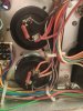
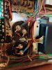
Ill post some pics I have so far. WhatsApp Image 2022-02-08 at 21.27.21 (1).jpeg WhatsApp Image 2022-02-08 at 21.27.21.jpeg WhatsApp Image 2022-02-08 at 21.27.21 (2).jpeg
 
Register to hide this ad
STOP playing the SX-1010 until the 2sa726 and 2sc1451 transistors in both power amplifiers have been replaced!!!

You are in the throes of their failure, and they WILL destroy your output transistors, emitter resistors and all associated circuits (yes, including the wires!!)!!!

They will burn wire, emit lots of magic smoke and make a real mess that will take a lot of effort and expertise to reverse.

NO FOOL'IN.... Not joking... totally serious....

The 1451's will turn your idle current on HARD, to the point where the big main capacitors will be drained in milliseconds, if not microseconds.
this type of surge destroys transistor dies (guts) before they even have time to get their cases hot!!
 
Damn Mark, You're getting faster in my old age, LOL...... I was gonna suggest that until I saw you already did.
 
@markthefixer and @larryderouin Thanks for the reply.

Aye Aye! I will not power up until those transistors have been replaced.
I have KSA992FBUs and KSC3503DSTUs in the mail.
I'll make sure to check for pins as you guys have already mentioned on other threads.
I'll update when I have made the replacements.

I know Q1-Q3 should be matched on each power amp board. Do they need to be matched between the two boards too?
 
Id also suggest you buy ricks power supply board to replace your awr054 if you can swing it. The originals all seem to be "well done" at this stage
 
Jstarz. Take a couple pictures of the POWER SUPPLY board and post. I've seen more than a few 1010 P.S. boards in the last few years that would make a cremation look like a new baby, while some look as good as it did when it left the factory. Most fall in between. Pioneer screwed up and placed it Underneath the unit, AND oriented it upside down which just traps the heat from the power transistors and resistors, and cooks everything.

The other thing with the P.S. is the clearance between the bottom panel and the closest component (usually the heatsink or one of the larger caps on the board) is btwn 1/8" and 3/16". The bottom is large enough and THIN enough to flex. When it flexes enough it WILL impinge on the P.S. board and crack the board. Be careful when putting it down on it's feet and make sure NOTHING is below it except for a flat board, shelf, etc.
 
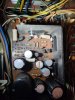
Here are some pictures of the power supply board. After looking at some pictures of some other boards, I guess this one would pass as a "medium"?
I'm planning on rebuilding it and maybe going for a new board in the future. I already spent quite a bit getting myself set up with the basic tools I will need for this kind of work.
Thanks for the tip about the clearance between the board and the bottom panel. I will definitely keep that in mind.

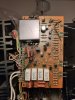
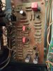
I'm also adding some pictures of the right amp board(I have already removed the 2sc1451s). Someone has obviously been in here before judging by the hack job they did on connecting the wires back to the pins but I can't tell what they did.

Since I'm still waiting on supplies from Mouser(many parts are back-ordered), my plan is to try to get the amp back to reasonable working condition before slowly continuing to a full restauration. I should have the replacements for the 2sa726s and 2sc1451s in the next few days.
I feel that since I am a novice, it might be a good idea to start the project on a working amp so that I can restore one part at a time and have an easier time backtracking if I mess something up.

WhatsApp Image 2022-02-12 at 23.09.43.jpeg WhatsApp Image 2022-02-12 at 23.12.01.jpeg WhatsApp Image 2022-02-12 at 23.14.26.jpeg WhatsApp Image 2022-02-12 at 23.11.28.jpeg WhatsApp Image 2022-02-12 at 23.14.16.jpeg
 
P.S. board, Medium Well. It can be upgraded. The best thing to do around the blackened area is to replace all of the resistors and mount them so there is about 1/4" of space between the body of the resistor and the board (crimp the leads). That'll keep the board a little cooler and allow air to circulate around the resistors to help cool them, rather than cook the board further. It'll last longer and run a bit cooler. Then you can rebuild the rest of the 1010 and possibly get Rick's p.s. board later.

Good idea on one board at a time, and test each for operation after work on it.

The Amp board pin connections (and any other board where the leads have been unwrapped and soldered back on). Usually we recommend to DeSolder the whole pin from the board, rather than unwrap the airtight lead wrap. As it's soldered, go ahead and desolder the lead from the pins (just enough of them to rotate the board out to work on.). There probably isn't enough slack in the wiring to wrap the pin more than a couple of turns to solder. But be aware that the solid core wire can and will be brittle and can break off inside the jacket without you realizing it until you power up (unless you do a continuity check on each wire from end to end. It's a pain but it will save on troubleshooting later.) If your OCD kicks in hard, you can purchase new 20-22ga solid core in the right colors and rewire if you feel you haven't got enough slack, or the wiring looks like shite!) Alternatively, you can remove each pin and thread the wire into the hole, fold it flat on the board and solder direct to the trace/pad.
 
Hi guys i hate to butt in I have the same Receiver had popping noise. Changed out transistors Q5 and 6 on both amp boards. I also replaced Q1, 2, 3 on both amp boards and matched 1 and 2 on both boards. Unit has sound now but when I first cut the receiver on I can hear a noise in the speakers not a loud pop but it is there. Once i hear the click and can hear the speakers it seems to go away, even when i turn volume up and down. When I shut the receiver off I turn down the volume and clear noise then it fades away. Not sure if I should post this here as I have been away for awhile but good to be back.
 
Stanley; Let's get you to start a new thread, so you have total attention for your rig, and jstarz rig gets it's due without confusion as to who is talking about what rig.
 
OK. So I got all the replacements in for the 2sa726s and 2sc1451s. I double-checked everything and turned it on with a dim bulb.
It passed the dim bulb test so I turned it on with no bulb. The relay clicks in after about 3 seconds and stays engaged.
I tried to listen to some FM on headphones but it does not play. I can only hear the radio playing very very faintly if I turn up the volume.

What should I be looking for next? any clues?
 
Haha I just jumped out of bed because I remembered I took out the preamp jumpers while working on the amp!
I have sound! I have a bit of a buzz/hum when no source is selected but It's a great place to start this restoration from.
I will play it for a while tomorrow and see that the pops do not return.
 
I listened to the radio for about an hour this morning with headphones. No loud pops and crackels yet. I really hope those stay away now that I have replaced the problematic transistors.
The three issues I did notice were:
1. The relay clicked out and back in after about a second. This happened twice in about an hour. I might have been able to hear an almost inaudible hum (very low frequencies) build-up before this happened, but I'm not sure about it. The relay takes about 3 seconds to click in after regular power up.
2. The right channel is louder than the left. I'm pretty sure this was the case before I started messing around. The balance knob needs to be set at about 10 o'clock for the two channels to even out volume-wise.
3. There is a background buzz audible also when no input is selected. Playing with the volume changes the loudness of the buzz and its pitch a little too.

Since I'm planning a pretty extensive restoration in any case, would it be best to just slowly work through the amplifier and see what issues I have left when I am done? Or are any of these issues "red lights" which should be addressed before I continue?

Thanks for all the help. I'm really enjoying this project.
 
1.) The Buzz/ Hum is most likely tripping the protection circuit out, and it resets. This could be from leaky filter caps (is the hum 60Hz or 120Hz, it matters, so find a recording of a 60Hz and a 120Hz tone and compare with your's). 3 seconds on a cold startup is on the low side (ideally it should be 4-7 seconds), which says that the protection board probably needs some work.

2.) This could be dirty switches, pots, connections OR caps and other transistors. Do a thorough cleaning of ALL SWITCHES, & POTS on the Front, and ALL of the RCA PLUGS on the back (including the pre out - Main in plugs). Re-Test.

3.) Make a set of shorting plugs (RCA Plugs off an old set of interconnect cables, with the center and outer wires twisted together to "short" the plug. Plug them in to PHONO (it won't hurt the system) and turn up the volume a bit. The Background buzz should go away. If it doesn't, you've got a problem in that section. Remove the plugs, and move to AUX and test again, then TAPE IN #1, and TAPE IN #2. )

This unit is 45 to 47 years old now. We know from experience that there are flaky and marginal transistors in the 1010, also dried out capacitors, and some baked or 1/2 baked resistors. The baked stuff is in the power supply. Relay develops pitted and corroded contact points and is replaceable (the part #'s are out there in threads.) Burnishing points on the relay is NOT recommended. You'll end up replacing it in a year or so.

Before anything else, DO THE POWER SUPPLY! This is the Engine that drives everything else. If the voltages aren't right, nothing works correctly. Rebuild the Amps and the protection circuit next. (add the 1n4007 flyback diode between pins 9 & 10 of the protection board. Cathode to pin 10). Then work your way back from the Amp board to the EQ board(phono preamp), doing each board in turn, and testing after each board!

BEFORE YOU DO ANY FINAL TESTING and Adjustments on the AMPS, we'll go over "TICKLING the DRAGON" and why it's important you NOT PISS HIM OFF!

Right now, Take some preliminary voltages on the power supply and write each down, post here in a VERTICAL Format, noting AC, DC, or GND. VOLTAGES need to be + or - (Example +16VDC or -39VDC, 12VAC, GND)

FORMAT
BOARD #
PIN # Schematic Voltage / Your Voltage.

EXAMPLE

AWR-054
Pin # 13 +35VDC / +37VDC
Pin # 10 -56VDC / -54VDC
Pin # 7 GND / GND (check ohms from Pin to chassis, post as Ohms)

Note: Voltages will usually NOT BE EXACTLY as shown on schematic. Allow up to 10% variance + or - of the "Bogey Value"(schematic value) . However your Input voltage at the plug should be as close to 120 as possible (use a variac) for prelim testing. If your wall voltage is 220VAC, or 230VAC, or 240VAC, Please note this and what area you are in. Country is fine (putting it in your profile helps immensely).

Build yourself a DIM BULB TESTER. Mine has a 3 way bulb setup so I can test small medium and large wattage receivers with a 50-100-150 bulb. The 1010 I've found reacts best to a 75 to 100W bulb, when on the DBT.

Regarding the Amp board Pins. You can slip some heatshrink tubing on each pin to isolate them from each other and still be able to use a meter on the pins thru the end.

I need you to check the Center Voltage (DC OFFSET) and BIAS on the Amp boards (this will have some effect on the protection circuit tripping.) DO NOT make adjustments, but post these measurements along with the P.S. voltages. Directions are in the Manual. (make a NOTE in the BIAS Section. CHANGE BIAS TO 25mv vs. 50mv as listed in Manual. Even Japanese Engineers make Mistakes. )
 
Hey Larry,

I think the buzz/hum sounds closer to a 60Hz.
I will get around to making some shorting plugs soon.

These are the measurements I'm getting today. I hope I'm doing this right. First time.

I am in Israel.
The wall outlet is 228 VAC.
Stepdown transformer(300W) is 115VAC. This is what I’m plugging into. I have a US model.

I'm measuring black lead to chassis. Red to pin.

AWR-054 C (expected values taken from AWR-054 A schematic)

Pin # 1 ? / 58.2VAC
Pin # 2 ? / 58.2VAC
Pin # 3 ? / 16.6VAC
Pin # 4 ? / 16.6VAC
Pin # 5 ? / 5.7VAC
Pin # 6 ? / +6.5VDC
Pin # 7 GND / GND (0 Ohms)
Pin # 8 +13.4VDC / +13.5VDC
Pin # 9 -13VDC / -13.4VDC
Pin # 10 -56VDC / -57.5VDC
Pin # 11 -24VDC / -23.8VDC
Pin # 12 GND / GND (0 Ohms)
Pin # 13 +35VDC / +35VDC
Pin # 14 +56VDC / +57.5VDC
Pin # 15 +24VDC / +26VDC


Chassis to wall outlet ground 47 VAC
Weird?


I have a fluke 101. It’s VDC setting has 3 zeros past the decimal point so it shows mVDC. I’m not sure if it is accurate enough though.
I don’t have a 8 Ohm dummy resistor so I didn’t hook anything up for this.

Right DC OFFSET 22 mVDC (Black to chassis. Red to pin 19)
Left DC OFFSET 7 mVDC

Right BIAS 0 mVDC (Black to pin 14. Red to pin 16)
Left BIAS 0 mVDC
Weird?


I should be using the chassis as black lead ground right? Even though this unit has no ground prong? I get very different numbers if I use the wall outlet ground.
 
I now have a 75W DBT set up. The bulb behaves as it should when I power up.
I also have some cheap speakers connected and have been listening to some music while on the DBT.

The voltages I get on the PS board while on the DBT are lower than the ones posted above (no DBT) which I gather makes sense.

At first I thought the DBT was only meant for checking for serious short circuits but after reading more threads I am realizing it can also give a form of protection from unplanned high bias after modification. I might have misunderstood though.


Is it safe for me to power up off the DBT throughout the restoration (assuming it powers up nicely on the DBT first)? Or is it just after special procedures like changing out the bias/offset pots that special attention is needed?


Does it make any sense that my BIAS is showing 0mVDC(see post #17)? Or am I doing something wrong?
 
Hi AK,

I finally got the parts and have the time to resume this project.
It would be great to have some guidance through the tricky parts.

I have rebuilt the power supply and protection boards according to @Super Noob 's thread (photos bellow).
The unit seems to be working at the moment (on a DBT) and nothing has exploded yet!
I plan to move on to the Amp boards next.

I noticed a weird clicky noise coming from somewhere in the back of the unit last night. I couldn't pinpoint where it was coming from. I noticed it seemed to happen when the FM was engaged even when the volume was down.
I made a recording here:
Maybe someone can tell what's going on here?


WhatsApp Image 2023-01-02 at 15.43.20.jpeg WhatsApp Image 2023-01-02 at 15.43.19.jpeg
 
Back
Top Bottom