

You are using an out of date browser. It may not display this or other websites correctly.
You should upgrade or use an alternative browser.
You should upgrade or use an alternative browser.
SX-1980 power supply problems
- Thread starter txturbo
- Start date

buildingnut
Active Member


THAT board is a hell of a mess. I would take away the soldering iron of anybody involved, and hand them a broom and tell them to stick with floors.
R212 looks smaller than 2w while r210 might be 2 watts. NEITHER is original. Not those green hot dogs.
Yea.. reminds me of a burnt pop tart.

Diode or Cap?
Here's a strange one... On the board that we are using for a template it appears that a diode has been installed in place of a cap. The part is C212. You can see in the picture we have marked it as D212 on the board however looking at the schematic and other pictures of the AWR-154 it should be a cap.

Here's a strange one... On the board that we are using for a template it appears that a diode has been installed in place of a cap. The part is C212. You can see in the picture we have marked it as D212 on the board however looking at the schematic and other pictures of the AWR-154 it should be a cap.
The layout is nearing completion.....
So here is a question:
Would it be better to replace the wire wraps for a set of connectors?
I sat with our technician that's laying out the board and we discussed the pro's and cons of such. The connector type would be a series of something similar to this:

The rating of the connector is 10 Amps.
PROS:
It makes installation and removal of the board much easier
CONS:
It's not how pioneer intended. I think it would cost more money.
It may have inferior connections compared to a soldered pin. I kind of doubt that it would be a problem.
Food for thought:
To get the board out you have a couple choices:
1. Attempt to remove the wire from the pin.
2. Cut the wire.
3. Desolder the pins from the board.
So the replacement sequence could be:
1. Use a set of wire markers and carefully mark each wire
2. Cut each wire off of the top of the wire wrap pin
3. Strip a bit off of each wire
4. Insert each wire into the new connector and screw it down
5. Remove the old board
6. Mount the new board
7. Mount the regulator transistors to the large heat sinks
8. Plug in the connectors
As an alternative the user could choose to install the original wire wrapped pins or put fresh pins on the board and plug the harness in with a mating connector. Since we are laying out the board slight adjustments to the pin placement could allow both.
Opinions, comments or suggestions?
So here is a question:
Would it be better to replace the wire wraps for a set of connectors?
I sat with our technician that's laying out the board and we discussed the pro's and cons of such. The connector type would be a series of something similar to this:
The rating of the connector is 10 Amps.
PROS:
It makes installation and removal of the board much easier
CONS:
It's not how pioneer intended. I think it would cost more money.
It may have inferior connections compared to a soldered pin. I kind of doubt that it would be a problem.
Food for thought:
To get the board out you have a couple choices:
1. Attempt to remove the wire from the pin.
2. Cut the wire.
3. Desolder the pins from the board.
So the replacement sequence could be:
1. Use a set of wire markers and carefully mark each wire
2. Cut each wire off of the top of the wire wrap pin
3. Strip a bit off of each wire
4. Insert each wire into the new connector and screw it down
5. Remove the old board
6. Mount the new board
7. Mount the regulator transistors to the large heat sinks
8. Plug in the connectors
As an alternative the user could choose to install the original wire wrapped pins or put fresh pins on the board and plug the harness in with a mating connector. Since we are laying out the board slight adjustments to the pin placement could allow both.
Opinions, comments or suggestions?

I concur. As a replacement Assembly, it would be easy to install and have better connections. The only disadvantage, if a guy wanted to retro-fit back to OEM sometime in the future, - with the shorter wire connections. But really, who is going to do that.

I also concur. The screw type connector(s) shown are a good idea.
Caveat: the connectors must group the wires in the same general physical areas that the original wire wrap pins, so that extra fiddle pharting isn't needed to make the connections from the existing wires.
10 amps is more than adequate for almost every connection on the secondary side.
Caveat: the connectors must group the wires in the same general physical areas that the original wire wrap pins, so that extra fiddle pharting isn't needed to make the connections from the existing wires.
10 amps is more than adequate for almost every connection on the secondary side.
More thoughts
Woke up with a couple more ideas...
1. I am working with an AWR-154 board. I noticed the schematic shows the AWR-155 as well. It would be great to make the board universal to work as a replacement for either type. Unfortunately I don't have the AWR-155 to look at. Anyone know what the differences are? I left my service manual at work and the PDF on line is really hard to read.
2. A few of the wire wrap pins have 2 or 3 wires. I would like to have individual connectors for each wire instead of trying to put multiple wires into a single screw down connector. I guess we just need to make sure that we have enough real estate on the board for the extra connections and length on the wires.
3. The area on the board where the fuses are located is a bit tight for landing the connector. I am thinking about changing the fuse type to a smaller physical size with the same rating to allow for a pinch more room.
1: I do not see the diff yet!!
2: I think that you only need the terminal block(s) for the outputs, so that you can isolate/remove the loads when troubleshooting and testing the regulator. Many of these circuits draw little I(ma's), a small TB using 100 mil or 3mm centers may work out better.
2: I think that you only need the terminal block(s) for the outputs, so that you can isolate/remove the loads when troubleshooting and testing the regulator. Many of these circuits draw little I(ma's), a small TB using 100 mil or 3mm centers may work out better.

Looks Good!! (I haven't done a deep inspection, yet)
Suggestion, if possible include additional radial cap pads on the three axial caps.
2x 220uf 160v, 3300uf 35v
The axial caps are limited to just one series. And becoming harder to find and more expensive (older technology to boot).
Since this looks like a double sided plated through board, 7.5mm and 10mm lead spacings (18mm clearance) as well as 10mm snap in spacings (22mm clearance) would be great so that we have some latitude for the "difficult" caps.
Just think about it?
Last edited:
Looks Good!! (I haven't done a deep inspection, yet)
Suggestion, if possible include additional radial cap pads on the three axial caps.
2x 220uf 160v, 3300uf 35v
The axial caps are limited to just one series. And becoming harder to find and more expensive (older technology to boot).
Since this looks like a double sided plated through board, 7.5mm and 10mm lead spacings (18mm clearance) as well as 10mm snap in spacings (22mm clearance) would be great so that we have some latitude for the "difficult" caps.
Just think about it?
Good point on the caps.. There may be sufficient room to replace single axial caps with pairs of radial ones. My concern is the height constraint of a single cap.. We will check it out.
Don't waste too much time looking at the board yet. It's changed a bunch already. I'll post the board and schematic when it's ready for a final review.
It's about flexibility, 7.5mm is the radial cap lead spacing on many of the candidates, while the rest are 10mm, and the balance of the candidates are snap-in caps.\ which while having a 10mm spacing, they use larger holes.
Last look before build..
OK...
Here is the board and schematic ready to be built.
We will send the design out to have the boards built tomorrow unless there is an error. We will get a minimum qty to make a test with. If it's good we will make more or modify till it's perfected.
Thanks to Mitch G for the layout! Also thanks to Glenn, Mark, Lee, RCS16, zebulon1, Solderiron, building nut, and others that helped with suggestions, comments and encouragement!
All of the parts except the power resistor and protection IC are available from Mouser. The IC is available from a few sources and the resistor is a digikey part.
Improvements from the original:
1. All wires are now on connectors for easy install and removal.
2. 80V reg transistors have been moved to the large heat sink.
3. The large electrolytic caps have mounting provisions for axial or radial.
4. The current source mod has been integrated into the board.
5. All of the substitute devices have been orientated with pad layouts that match the pinout of the device.
6. The board has been silkscreened with components id.
7. The board has an internal ground plane. This is a bit subtle when you look at the layout.
8. Q203 and Q205 have larger heat sinks
9. The board can be built from 100% new components.

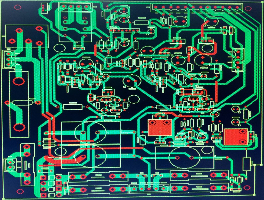


OK...
Here is the board and schematic ready to be built.
We will send the design out to have the boards built tomorrow unless there is an error. We will get a minimum qty to make a test with. If it's good we will make more or modify till it's perfected.
Thanks to Mitch G for the layout! Also thanks to Glenn, Mark, Lee, RCS16, zebulon1, Solderiron, building nut, and others that helped with suggestions, comments and encouragement!
All of the parts except the power resistor and protection IC are available from Mouser. The IC is available from a few sources and the resistor is a digikey part.
Improvements from the original:
1. All wires are now on connectors for easy install and removal.
2. 80V reg transistors have been moved to the large heat sink.
3. The large electrolytic caps have mounting provisions for axial or radial.
4. The current source mod has been integrated into the board.
5. All of the substitute devices have been orientated with pad layouts that match the pinout of the device.
6. The board has been silkscreened with components id.
7. The board has an internal ground plane. This is a bit subtle when you look at the layout.
8. Q203 and Q205 have larger heat sinks
9. The board can be built from 100% new components.


Why use the MY2 relay layout? The original speaker relay, though having the same pinout as the modern Omron MY2, was capable of over twice the current. If you have the freedom of new design, at least set it up where the speaker relay is an LY2-0-DC48.
Same sort of deal with the soft-start relay...the LY1 is a major PITA to locate. Replace with an LY2. Either the LY2-0-DC48 or the LY2-DC48.
Same sort of deal with the soft-start relay...the LY1 is a major PITA to locate. Replace with an LY2. Either the LY2-0-DC48 or the LY2-DC48.
Why use the MY2 relay layout? The original speaker relay, though having the same pinout as the modern Omron MY2, was capable of over twice the current. If you have the freedom of new design, at least set it up where the speaker relay is an LY2-0-DC48.
Same sort of deal with the soft-start relay...the LY1 is a major PITA to locate. Replace with an LY2. Either the LY2-0-DC48 or the LY2-DC48.
Good catch.. :yes:
We planned on using the MY2-02-DC48 and LY1-0-DC24.
We need to look at the changes made to use the 24V relay and revert back. Probably just make them the same LY2-0-DC48.
If we're going to use different relays, the 48v specification is a limiting and sourcing pita.
We can tap raw DC 24v and use 24v relays for both. LY2-0-DC24 NO R102, R308 3.3k 2watt metal oxide dropping resistors needed.
Call it 38mA each, instead of 19mA each from the 99-106v line and throwing half the wattage (voltage) away as heat.
I have been doing so in my repairs for a while. No problems.
I HAD to use ly1-0-dc24 relays because the 48v relays became difficult to find.
Last edited: