• The move to the new server is done. There are some software and database maintenance updates in process. This has us passing the hat around to help out. We appreciate any donations. Seriously, even a dollar helps. The payment page may be found here - https://www.audiokarma.org/support.html

SX-3900 Powers on, but no audio output...

Also... just thought of this... I have both pre-out jumpers out right now. Should I re-insert them at this point?

For now leave em out, but it really doesn't matter. Until we get juice back in....

Re: C9 up and down are relative terms, but i think neg is up, as long as the row of pins on one edge of the board is also up. The pos side of the cap is grounded because pin 26 is a -13v IIAC.
EDIT: AH HAH, my bad, NOT 28, 26....... 28 is part of the soft start circuit elsewhere on the board, sorry there, I misread the 26 on my blowup of the pc board, and didn't look on BOTH sides: " 27 28/6?? 25


Read the same (yellow, green orange) AC voltages, BUT at the diode connections i previously mentioned. Then read the DC on the other side of the diodes. both AC and DC readings are ground referenced.

Because those ac voltages look good. next step dc.

Funny thing is the big transformer with the red leads going to the big caps should really light up that bulb!!

Oh, on the power supply, you are using jfets from ampslab for Q1 & Q2?
 
For now leave em out, but it really doesn't matter. Until we get juice back in....

Re: C9 up and down are relative terms, but i thing neg is up, as long as the row of pins on one edge of the board is also up. The pos side of the cap is grounded because pin 26 is a -13v IIAC.
EDIT: AH HAH, my bad, NOT 28, 26....... 28 is part of the soft start circuit, sorry there, I misread the 26 on my blowup of the pc board, and didn't look on BOTH sides: " 27 28/6?? 25
No sweat. I have a really nice manual that is very clear, from Rick at Stereo Manuals, so no real difficulty reading the numbers... except for my almost 44 year old eyes...:sigh:)

Read the same (yellow, green orange) AC voltages, BUT at the diode connections i previously mentioned. Then read the DC on the other side of the diodes. both AC and DC readings are ground referenced.(So I will check both the anode for ac and the cathode for dc on D2 D3 D4 D5 D7 & D8... is this correct?)

Because those ac voltages look good. (GREAT!):yes: next step dc.

Funny thing is the big transformer with the red leads going to the big caps should really light up that bulb!!

Thanks again for all your help... MOST appreciated.
 
So I will check both the anode for ac and the cathode for dc on D2 D3 D4 D5 D7 & D8... is this correct?)

The AC side is specified, anode by default and cathode explicitly mentioned.

The ac going in the anode will have positive dc at the cathode.(d2,d4,d7, d8)
the ac going in the cathode will have negative dc at the anode.(d3, d5 )

If you get good DC, about +70v (d2,d4 cathodes) , -70v(d3,d5 anodes) and +20v(d7,d8 cathodes), check the other sides of the three 2.2 ohm resistors (r4, r5, r23) that feed the regulators. This is raw dc, so it can vary quite a bit and still be ok.

what about Q1 & Q2 jfets? you missed that on my post...
sometimes these posts are a work in progress where stuff flies back and forth too quick.

I'm off for tonight (1 am here) so if there is more you want to do, figure out why the primary of the big transformer isn't energized, up to disconnecting a wire for the primary and measuring the dc resistance independently of anything else.
It's the brown wire going to pin 3 of the board with the relay and big caps. check the resistance between pins 3 and 4.
The other wire from the transformer may not even go to that board. It may be directly connected to pin 1. Looking at one here, the pin 3 COULD have come loose, you were soldering that trace (thermal fuse) an inch away and moving the board around too.
 
The AC side is specified, anode by default and cathode explicitly mentioned.

The ac going in the anode will have positive dc at the cathode.(d2,d4,d7, d8)
the ac going in the cathode will have negative dc at the anode.(d3, d5 )

Ah... thanks for clearing this up. I will check them all.
 
The AC side is specified, anode by default and cathode explicitly mentioned.

The ac going in the anode will have positive dc at the cathode.(d2,d4,d7, d8)
the ac going in the cathode will have negative dc at the anode.(d3, d5 )

D2 59vac at anode & 76vdc at cathode
D4 59.5vac at anode & 76vdc at cathode
D7 18.8vac at anode & 23vdc at cathode
D8 19vac at anode & 23vdc at cathode
D3 -78vdc at anode & 58.7vac at cathode
D5 -78vdc at anode & 59.2vac at cathode


If you get good DC, about +70v (d2,d4 cathodes) , -70v(d3,d5 anodes) and +20v(d7,d8 cathodes), check the other sides of the three 2.2 ohm resistors (r4, r5, r23) that feed the regulators. This is raw dc, so it can vary quite a bit and still be ok.

r4 9vdc
r5 -55vdc
r23 23vdc (both sides of the resistor) (r23 checked good with 2.6 ohms - in circuit)


what about Q1 & Q2 jfets? you missed that on my post...
(Yes, the Ampslab 2SK30A-Y are on Q1 and Q2)
sometimes these posts are a work in progress where stuff flies back and forth too quick.

I'm off for tonight (1 am here) so if there is more you want to do, figure out why the primary of the big transformer isn't energized, up to disconnecting a wire for the primary and measuring the dc resistance independently of anything else. (Do you mean to disconnect both the brown & white wires for the big transformer and measure resistance across those leads?)
It's the brown wire going to pin 3 of the board with the relay and big caps. check the resistance between pins 3 and 4. (There is continuity between pins 3 & 4 on the Rectifier board, with no discernible resistance. I also checked the wires for continuity and the traces on the Rectifier board - all with good continuity)
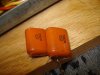
The other wire from the transformer may not even go to that board. It may be directly connected to pin 1. (The white wire IS directly connected to pin 1 on the rectifier board, and there is good continuity between that white wire and pin 1 and the corresponding trace on the board) Looking at one here, the pin 3 COULD have come loose, you were soldering that trace (thermal fuse) an inch away and moving the board around too. (I did not solder a new thermal fuse on that board, but did put in new main caps and replaced the 2.2 m ohm resistor, c1, c2, c5 (with ceramic caps) and the caps across pins 7-10-14 of the Rectifier board. Please see attached photos of that replacement. The caps across pins 7-10-14 are Polypropylene Film Caps 0.22uF 250v, Mouser P/N 505-MKP20.22/250/5 Not sure if those might be throwing the power off? I have the old caps if needed for replacement (see 2nd picture)

All voltages referenced to chassis ground.
 

Attachments

  • Caps1.jpg
    Caps1.jpg
    34.9 KB · Views: 48
  • Caps2.jpg
    Caps2.jpg
    24.4 KB · Views: 45
AS a shortcut, CAREFULLY when powered up, measure the DC voltage at each of the four pins of the two big capacitors, referenced to ground, to see if they are getting any charge. Two are grounded, so they will read millivolts or less. The others will be at about plus and minus 60v.

Then if they aren't showing any voltage, VERY CAREFULLY measure the 120v AC at the actual brown and white transformer wire connections.

Ok, as far as the voltages, everything before R4 and R5 looks good.

R23 looks great with about the same voltage on each side.

R4 and R5 look terrible.

R4 is a 2.2 ohm resistor and should have about 71v on both sides. If you were to measure the voltage across it (one voltmeter lead on each resistor lead) while live, and use ohm's law, you could calculate the current drain of that power supply voltage.

R5 is the same for the negative voltage.

Now I am at a dilemma. At those voltage differences
R4: (D2 76vdc at cathode) and 9v after it is (76 -9) / 2.2 = 30 amps
R5: (D5 -78vdc at anode) and -54v after it is (-78 - - 54) / 2.2 = 11 amps
which would have the lightbulb glowing and the resistors vaporizing.

Please check the actual resistances of R4 & R5. They have probably been cooked to a higher value.

When operating there should be about 150 milliamps of current flowing at each resistor, so reading a voltage across 2.2 ohms yields about 0.33 volts across R4 and also R5. (which is why we don't try to subtract the 71.0 and 70.6 readings to get it, we read it directly at the resistor.)

sx-3900 power supply current draws as per schematic:
(+54 is 60mA, +32 is 60mA) total 120mA
(-54 is 40mA, -32 is 60mA, -21 is 20mA, -13 is 20mA) total 140mA
(as an exercise, try to find those numbers on the power supply schematic, the hard one uses -32v and an 11 volt D14 zener diode to make -21)
 
Good news and bad news...

AS a shortcut, CAREFULLY when powered up, measure the DC voltage at each of the four pins of the two big capacitors, referenced to ground, to see if they are getting any charge. Two are grounded, so they will read millivolts or less. The others will be at about plus and minus 60v. (They get -61 vdc on the c3 neg side and 62 vdc on the c4 pos side. The other positions are nil, or less than 0.1mv dc)

Then if they aren't showing any voltage, VERY CAREFULLY measure the 120v AC at the actual brown and white transformer wire connections. (Get 118vac on these points)

Ok, as far as the voltages, everything before R4 and R5 looks good.

R23 looks great with about the same voltage on each side.

R4 and R5 look terrible.

R4 is a 2.2 ohm resistor and should have about 71v on both sides. If you were to measure the voltage across it (one voltmeter lead on each resistor lead) while live, and use ohm's law, you could calculate the current drain of that power supply voltage.

R5 is the same for the negative voltage.

Now I am at a dilemma. At those voltage differences
R4: (D2 76vdc at cathode) and 9v after it is (76 -9) / 2.2 = 30 amps
R5: (D5 -78vdc at anode) and -54v after it is (-78 - - 54) / 2.2 = 11 amps
which would have the lightbulb glowing and the resistors vaporizing.

Please check the actual resistances of R4 & R5. They have probably been cooked to a higher value. (Now for the bad news... ROOKIE MISTAKE MADE BY ME.:tears: I had replaced the 2.2 ohm resistors with 2.2k resistors in the r4 and r5 positions. I replaced them with 2.2 ohm (although not metal film, but carbon film 1/2 watt. I did not have 2 metal film 2.2 ohm 1/4 watt resistors in the shop. Will the carbon film 1/2 watt resistors suffice, or should I get metal film 1/4 watt to replace them with?) and re-checked all voltages.)

When operating there should be about 150 milliamps of current flowing at each resistor, so reading a voltage across 2.2 ohms yields about 0.33 volts across R4 and also R5. (which is why we don't try to subtract the 71.0 and 70.6 readings to get it, we read it directly at the resistor.)

sx-3900 power supply current draws as per schematic:
(+54 is 60mA, +32 is 60mA) total 120mA
(-54 is 40mA, -32 is 60mA, -21 is 20mA, -13 is 20mA) total 140mA
(as an exercise, try to find those numbers on the power supply schematic, the hard one uses -32v and an 11 volt D14 zener diode to make -21)

Now for the NEW voltage readings after replacing the 2.2k with the proper 2.2 ohm resistors in the r4 & r5 spots. Readings appear more consistent now at least.

D2 50.6vac at anode & 56vdc at cathode
D4 50.6vac at anode & 56vdc at cathode
D7 16.7vac at anode & 19vdc at cathode
D8 16.7vac at anode & 19vdc at cathode
D3 -65vdc at anode & 50.6vac at cathode
D5 -65vdc at anode & 50.6vac at cathode

r4 56vdc
r5 -65vdc
r23 19vdc (both sides of the resistor)

Couple of other interesting points now.

1. Still no soft start relay.
2. Now the flouroscan power meter (left side) illuminates fully (although somewhat dim as to what it would normally be. DBT effects???).
3. All of the selector lights illuminate (dimly) when the respective selector switch is depressed (FM/AM/AUX/PH2/PH1)
4. The DBT still does not illuminate (noticeably) at any point.

Oh, and am I safe to believe that the caps I have on the Rectifier board on pins 7-10-14 are acceptable parts and likely not the/an issue?

Other than that... is where it stands. I apologize for the resistor debacle and as always, appreciate the hell out of the assistance.
 
Ok, the raw dc (+/- 63v on c3, c4) from the big transformer (the actual output power) is ok.

Leave the 2.2 ohm resistors you have in there alone. They are probably just for current measurement, crude fuses and maybe some obscure power down function. They are in no position for any real inrush current limiting.

The caps you removed could have had "safety specifications" like X or Y and an underwriters laboratory stamp on them. They're called "death caps" and have certain specs for connection to the power line. If they do, put them back, in the exact same position - x and y matter, they are failure modes. Non-electrolytic caps rarely need replacement. There are narrow cases when technology has improved - I can't think of any for the 3900. Some film caps across C3 & C4 wouldn't hurt - but these have less inductance than some others.

The R4 positive voltage is too low for the 54v regulator to function, the R5 negative voltage is ok.

Recalculating:
R4: (D2 76vdc at cathode) and 9v after it is (76 -9) / 2200 = 30mA
R5: (D5 -78vdc at anode) and -54v after it is (-78 - - 54) / 2200 = 11mA
no help...

We need to measure across R4 and R5 to get an idea of what current is being drawn, as to why the R4 voltage is so low. One probe on each lead of the resistor. I have to see if there is too much current being drawn somehow, or if there is a regulator problem.

Then we need to measure the regulated supply voltages:
pin 22 +54v
pin 23 +32v
pin 20 -54v
pin 24 -32v
pin 25 -21v
pin 26 -13v

Don't sweat voltage variations too much, everything keys off the +54v supply or it's 14v reference, and the differences will be very illuminating to me.

The speaker selector lamps run off a different power than the function lamps, are they brighter?
 
Good morning Mark. Here is what I have now.

Ok, the raw dc (+/- 63v on c3, c4) from the big transformer (the actual output power) is ok.

Leave the 2.2 ohm resistors you have in there alone. They are probably just for current measurement, crude fuses and maybe some obscure power down function. They are in no position for any real inrush current limiting.

The caps you removed could have had "safety specifications" like X or Y and an underwriters laboratory stamp on them. They're called "death caps" and have certain specs for connection to the power line. If they do, put them back, in the exact same position - x and y matter, they are failure modes. Non-electrolytic caps rarely need replacement. There are narrow cases when technology has improved - I can't think of any for the 3900. Some film caps across C3 & C4 wouldn't hurt - but these have less inductance than some others. (There are no additional markings on those caps, other than what you can see in the picture I attached previously. But, I replaced the originals just to ensure no issues with the new replacements, in their original orientation, with absolutely no change in behavior upon power up. For now, the originals remain installed)

The R4 positive voltage is too low for the 54v regulator to function, the R5 negative voltage is ok.

Recalculating:
R4: (D2 76vdc at cathode) and 9v after it is (76 -9) / 2200 = 30mA
R5: (D5 -78vdc at anode) and -54v after it is (-78 - - 54) / 2200 = 11mA
no help... (I think you may have been using the "old" voltage readings here. The new readings - after the 2.2 ohm resistor replacements - are as follows... The D2 cathode voltage is actually +56vdc and after R4 the voltage is +56vdc. The D5 anode voltage is actually -65vdc and after R5 the voltage is -65vdc)


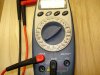
We need to measure across R4 and R5 to get an idea of what current is being drawn, as to why the R4 voltage is so low. One probe on each lead of the resistor. I have to see if there is too much current being drawn somehow, or if there is a regulator problem. (I am not too sure how to do this, little green in this area. I think you want me to measure DC CURRENT and NOT DC VOLTAGE. So I switched out the red lead on my meter to the uAmA spot and turned the dial to the DC 200m setting shown in the picture. Is this the correct setting and lead placement for this test? If so, I get 100.5 across R4 and 7.6 across R5.)

Then we need to measure the regulated supply voltages:
pin 22 +54v (Have +18vdc)
pin 23 +32v (Have +10vdc)
pin 20 -54v (Have -19vdc)
pin 24 -32v (Have -10.7vdc)
pin 25 -21v (Have -0.62vdc)
pin 26 -13v (Have -7.5vdc)

(Once again... the other side of R4 and R5 are as follows:
R4 +56vdc
R5 -65vdc)


Don't sweat voltage variations too much, everything keys off the +54v supply or it's 14v reference, and the differences will be very illuminating to me.

The speaker selector lamps run off a different power than the function lamps, are they brighter? (Yes, they are brighter than the function lamps. About the same intensity as the 3 display lamps. Same circuit as those I believe, right?)

POST HAS BEEN EDITED AND IS COMPLETE. THE EDITS ARE SHOWN IN BOLD AND UNDERLINED ABOVE.


Thanks again.
 

Attachments

  • Meter.jpg
    Meter.jpg
    34.5 KB · Views: 20
This is the quick reply, it will be added to.

Yes I was using the old readings, in an attempt to establish an idea of the amount of current flowing through the 2200 ohm resistors.

You are correct that I wished to measure current in regards to the 2.2 ohm resistors, and the method you used, while unconventional, did yield rough results. The intent was to read about 0.33 volts across the 2.2 ohm resistor and calculate the current using ohms law.

The meter, when measuring current, does a voltage reading across a resistor internally shunted across the probes, essentially in parallel with the 2.2 ohm resistor. Thus SOME of the current flows through the 2.2 ohm resistor and the rest of the current flows through the meter's shunt - introducing an UNKNOWN error because we may not know the exact resistance of the shunt in the meter.

That's not a problem for now, I was looking for a huge current draw indicative of a short circuit and the rough voltage readings seemed to show a volt or less of differential voltage across the resistor.

I will be back to address the regulated voltages. I suspect the 14v reference - it might be in backwards? I have to look closer.

ARRRRRRRGGGGGGGGGGHHHHHHHHHHH........... I forgot to include pin 19 at 12.8v and pin 11 at 5.5v !!!

Pin 19 gives me an indirect read for the 14v D6 zener diode's voltage - the key to everything........

So, what is the voltage across D6? It should be 14v, it may be between 4.5 and 5v.


When this disappears, the post is complete
 
I will await your finished post. In the interim, I checked the DC voltage (with the DMM at the 2v DC setting) across both R4 and R5, and here is what I got.

0.44vdc across R4
0.03vdc across R5

Does this correspond???
 
Just saw your new info that you need. Let me go check those points real quick. I should have them posted in the next 10-15 minutes or less.
 
I will await your finished post. In the interim, I checked the DC voltage (with the DMM at the 2v DC setting) across both R4 and R5, and here is what I got.

0.44vdc across R40.44/2.2 = 200 mA
0.03vdc across R50.03/2.2 = 14mA

Does this correspond???

OK, here are the additional readings.

Pin 19 has 8vdc
Pin 11 has 2.75vdc
D6 across leads has 9.5vdc

The R4 current drain is a bit high, hard to tell with the lowered voltage.
The 32v regulator is working, taking 18v to 10v proportionately.

It COULD be pulling down the 14v zener, or the Q10, Q9 combination could be doing it.

Try opening up the wire on pin 22 and then read the pin 22 voltage again. It ONLY runs the amp. so we may have amp problems to deal with yet.
 
Hoooray! Took the wire off of Pin 22 with 54vdc on that pin and it all lights up and the soft start relay kicks in. Amp board issue I take it... Now what?:yes::yes:
 
Back
Top Bottom