
• The move to the new server is done. There are some software and database maintenance updates in process. This has us passing the hat around to help out. We appreciate any donations. Seriously, even a dollar helps. The payment page may be found here - https://www.audiokarma.org/support.html

SX-3900 Powers on, but no audio output...

I went ahead and re-checked all the voltages (with Pin 22 disconnected). All referenced to chassis ground and VDC. Here are the results:

Pin 1 0
Pin 2 0
Pin 3 0
Pin 4 -9.21
Pin 5 -13.40
Pin 6 -13.40
Pin 7 6.72
Pin 8 6.72
Pin 9 6.72
Pin 10 6.72
Pin 11 5.00
Pin 12 12.3
Pin 13 17.7
Pin 14 -0.395
Pin 15 -0.396
Pin 16 0
Pin 17 0.35
Pin 18 0.37
Pin 19 13.06
Pin 20 -55
Pin 21 0
Pin 22 55
Pin 23 32
Pin 24 -32
Pin 25 -18.1
Pin 26 -13.8
Pin 27 0

D2 anode 51.3vac cathode 61vdc
D4 anode 51.7vac cathode 61vdc
D7 anode 16.4vac cathode 18vdc
D8 anode 16.7vac cathode 18vdc
D3 anode -60vdc cathode 0.67vac
D5 anode -60vdc cathode 0.67vac

R4 63vdc
R5 -63vdc
R23 18.33vdc
 
Hoooray! Took the wire off of Pin 22 with 54vdc on that pin and it all lights up and the soft start relay kicks in. Amp board issue I take it... Now what?:yes::yes:

I need time to think. That much current would heat something up significantly.

There are a lot of resistors in the way of the current:

two 100k: R115, R116 for the input differentials.

four 1k(0.7v to 1v, ~1mA) & four 1.3k(1.3v, 1mA) on the Q121, Q123, Q122, Q124 current sources. This is the most "independent" circuit on the board. It's biasing the NSA circuit that's part of the bias generator.

3k(2.1v, 0.7mA) & 220(1.6v, 7mA) ohms on the Q115 & Q116 current sources. No typos: 0.7mA and 7mA....
the Q109 & Q110 on the opposite side (corresponding to the Q123, Q124 positions)are the VAS stage, just for informational sake. This is the bias generator and Voltage Amplification stage.

Q101 and Q102 have direct connections to the collectors and bases, with 330k pots (VR1 & VR2) and 68k or so on the emitters to -54v for the offset compensation circuit. You didn't crank those down to zero did you? Set them to maximum ohms initially.

Then there's the two SETS of bias pots:
first the 100 ohm set of VR3 & VR4 - set those to zero ohms.
second the 100k ohm set of VR5 & VR6 - set these to maximum MINIMUM ohms.
EDIT 2022: minimum ohms!!!

Hopefully we didn't fry any transistors - did you smell anything "hot"?

Do these settings, reconnect pin 22 and watch the pin 22 voltage as it's turned on.

Where I mention a resistance, voltage and current, those are typical values AT that component, the voltage across the component (one side will be at the regulated voltage of 54) for the appropriate amount of current as designed.

Other than those circuits, the +54 goes to drive the protection relay, 20mA worth. D133 (across the protection relay coil), is it in right? It would draw a LOT more current if it were facing the other way.
 
Last edited:
I set them per the SM upon completion of the board rework...

VR3, VR5, VR4 and VR6 fully counterclockwise

VR1 and VR2 to the center position

No. I did not smell anything hot or burning. I left the power on only long enough to take the voltages and then turned it of each and every time I tested a component.

Are these in the correct position that you want me to put them in, or off???

Is maximum clockwise or counter or center on VR1 and VR2?
 
I set them per the SM upon completion of the board rework...

VR3, VR5, VR4 and VR6 fully counterclockwise

VR1 and VR2 to the center position

No. I did not smell anything hot or burning. I left the power on only long enough to take the voltages and then turned it of each and every time I tested a component.

Are these in the correct position that you want me to put them in, or off???

Is maximum clockwise or counter or center on VR1 and VR2?

Use the ohmmeter, cw - ccw etc can sometimes be a problem. That's why I say ohms...
Other than that I would have to look closely at the pcb pattern to see which side (cw, ccw) the wiper is connected to.
The pattern is the same for all 4.


VR1 & VR2 centered is reasonable.

VR3 & VR4 at minimum ohms is minimum bias
VR5 & VR6 at maximum sets the minimum voltage on D113, D115. Maybe they want the maximum....

somehow "VR3, VR5, VR4 and VR6 fully counterclockwise" rings a bell.

I need more time to think, probably will add a current limiting resistor at pin 22 to cut the load while we measure, to keep the 54v in place.
 
OK. I set the VR1 and VR2 to max ohms, which is fully cw

Set VR3 and VR4 to minimum ohms, which is fully ccw
Set VR5 and VR6 to max ohms, which is fully cw

I verified the D133 orientation and it is correct.

Reconnected the pin 22 wire, and it is back to its old antics...

No soft start relay, no frequency display and dim power meter display... just as before.

Oh, and the pin 22 voltage is at 18vdc...
 
somehow "VR3, VR5, VR4 and VR6 fully counterclockwise" rings a bell.

I need more time to think, probably will add a current limiting resistor at pin 22 to cut the load while we measure, to keep the 54v in place.

put a 500 ohm or so (470 ohm) 5 watt resistor between pin 22 and it's wire - that will limit the current. try grounding the wire end of the resistor first (no wire connected) so that the pin 22 voltage goes through the 500 ohm resistor AND see if pin 22 stays about 54v.

This has two purposes, one is to be sure the power supply CAN deliver 100 mA current correctly.

Then connect the wire to the resistor, take voltage readings on both sides of it.

take quick voltage readings on each of those amplifier resistors (8:55 pm post) in hopes of finding where that current is going. It's going somewhere. Any possible shorts where the board is mounted?

What are the voltages on each side of D111, D112, D117, D118 ?

What are the voltages on each side of R196 (560 ohms 1/2 watt)?

(it's gotta be a transistor in backwards. look for the heat on the board when freshly powered off)
 
Well, you got me on that one. I don't have any 470 or so 5 watt resistors to do that. :no: Closest I have are 3.3 ohm 25 watt ceramic resistors I bought in case I needed to replace the one on the Rectifier board. The highest wattage resistors I have otherwise are 1 and 2 watters. Dunno if Rat Shack might have them??? Or I will find one tomorrow somewhere. I have many options here in the Southern California area fortunately.

Let me get this correct... You want me to connect the resistor to pin 22, then ground the other side of the resistor and power on the receiver? Then check pin 22 for the 54 vdc while it is grounded?

Or am I confused???
 
Well, you got me on that one. I don't have any 470 or so 5 watt resistors to do that. :no: Closest I have are 3.3 ohm 25 watt ceramic resistors I bought in case I needed to replace the one on the Rectifier board. The highest wattage resistors I have otherwise are 1 and 2 watters. Dunno if Rat Shack might have them??? Or I will find one tomorrow somewhere. I have many options here in the Southern California area fortunately.

Let me get this correct... You want me to connect the resistor to pin 22, then ground the other side of the resistor and power on the receiver? Then check pin 22 for the 54 vdc while it is grounded?

Or am I confused???

Spot on. It is a load test to be sure the regulator can deliver the appropriate amount of current. BEFORE we start futzing around with the amp section.

After that it will limit the amount of current the amp can pull if it is bad.

nite nite
 
Bad news... The DBT bulb lights brightly now. NOT the goal I know... There was a very short duration short on one of the output transistors attached to the aluminum heatsink. I saw the connector loose (damaged plastic connector, although I had it temporarily taped up) and some sparks at it. This was with the power turned OFF when I was checking the security of all connections.

Once I made sure it was all connected well, I powered it back on and the DBT was very bright, so I immediately turned off the power.

I pulled the 3 wire connector plug that goes to Pins 13, 14, 15 on the Power Amp Board and then powered it on and the DBT bulb did NOT glow. I plugged that connector back in and the DBT bulb was bright again.

I think that the output transistor Q4 might have blown, or something on the power amp board??? It was a new set of Sanken transistors... :tears:

I have the 470 ohm resistor now. I can do the initial pin 22 through resistor to ground test, but should I continue on with the test with that resistor connected in series with the wire from Pin 22 of the power supply board? Stuck now as to what to do with the additional checks requiring the power amp board to be connected from Pin 22...

This SX-3900 WILL NOT WIN ME!!!!
 
OK. I placed the 470 ohm resistor on Pin 22, with the other lead to chassis grnd. Got 49vdc and the receiver still lit up fully and the soft-start relay kicked in.

I have not done any other checks with the power amp board connected until I get advice on how to approach it.

I went over each and EVERY transistor by part number and "E" emitter orientation on the power amp board (twice) by the schematic and the silk-screened board markings, with each transistor data sheet to compare to. They all are installed in the correct orientation (emitters on E). The schematic matches up with the PCB silk-screened markings, as far as I verified.

I also checked continuity on the OLD output transistors, which are not installed/fully disconnected, just to see if they were consistent. They were not. Some were shorted on all 3 pins and others were open on all three pins. I compared the 2SA1076 together, and the 2SC2526 together for consistency. Not consistent... if that means anything at all for troubleshooting. Likely not, due to the Power Supply and Power Amp boards being completely shotgunned.

Just trying to check anything and everything I can, in a safe manner... mostly verification things.
 
OK, what I would like to do is get the 8 old transistors readings on the dmm diode test, the full 6 combinations on each: OL's and zeros and valid Mv readings - warts and all.
Then I'd like to do the same with the new sankens, including the one that may have gotten zapped.

http://www.audiokarma.org/forums/showthread.php?t=43186 post #11 for explicit testing and reporting format, feel free to cut and paste - then edit in your readings.

What is the condition of the socket you had trouble with? I have disassembled (and reassembled, and with the wire wraps - not recommended ) these before so I have a very clear idea of how they are constructed.

Did you try deoxiting these sockets, and cleaning them :deoxit into a business card thickness of paper and used to burnish them.

We may want to try opening up the 560 ohm resistor that energizes the protection relay later on.

Get familiar with where to probe on the board to read the amplifier outputs BEFORE the protection relay interrupts them. Hint - near those big coils are some convienent ten ohm (r187, r188) resistor leads. We will ber lookingf for the dc offset voltages - millivolts when ok, tens of volts when not.

Now is not yet the time to apply power to the amp, when we do it will be through that 470 ohm resistor.

Now here is something that is VERY important:
On that amplifier board, the +54v comes in on Pin 5. That trace has a jumper that connects it to a trace running around the front EDGE of the pc board. It also arcs along both sides, just shy of the corners where the screws go through. It also has a jumper connecting to a trace that goes through the center of the board, heading over to the relay and the protection circuits.

We may just open up those jumpers to try to localize the current drain. Then the meter can be set to read current, and substitute for the jumpers.
We could even stick in that 470 ohm resistor.

BUT:
I NEED you to trace every millimeter of that +54v trace (since you did do a shotgun change out) and CLEAN everything away from it, don't hurt the green protective coating, pay special attention to all the solder joints. Flux and anything that could be hiding a short. In the process you will get VERY familiar with all the resistors we will be making voltage readings across.

Since the corresponding -54v supply's current was way lower than the positive 54v 's current, the return path for the +54v's current HAS to be through GROUND.
 
SX-3900 induced 3 AM insomnia... Don't let the 05:06 AM Illinois timestamp fool you, it's indeed 3 AM here...

Questions:
1. Do you want me to remove the Sankens from the heatsink prior to testing them with the meter? Some of the pins on them currently have continuity to the heatsink. (Problem?)

2. Did the Pin 22 with the 470 ohm resistor to ground pass the current check for the power supply board?

3. Is there a safe and effective way to ensure that either residual (cap) voltage is discharged or the boards are isolated when moving around the power amp board and fuse block (if I have to remove the Sankens), to prevent possibly further shorting something out to ground, etc? I know to be as careful and diligent as possible, but want to try and avoid any further setbacks.

The damaged connector is cracked and I had it taped together. One of those pins popped out and shorted (I believe) between a pin of the transistor and the heatsink. I did Deoxit (D5N) them well and used a small, appropriate sized metal piece as a burnishing device, and all appear to be making good contact.

I would love to directly attach these somehow. Those plastic connectors, with the corresponding heat they obviously get repeatedly is a poor design IMO. I know EW had mentioned in a post on AK here about an alternate connection option of some sort for a different model Pioneer. Maybe it might work on the SX-3900 output transistors?

I thoroughly cleaned all the boards of flux and that yellowish hardened coating from the boards after component replacement. So they, along with the power amp board are extremely clean. I am familiar with the pin 5 trace and see how it could become shorted somewhat easily. I verified that the composite isolation washers are in place between the power amp PCB and the heat sink mount. I did an ohm/continuity check there for a short, but found none. And I will lend a microscopic eye on the power amp board and all traces for any issues.

I will await your response to ensure that I am testing them (output transistors) properly. I checked the old output transistors, but will wait to post the results along with the Sankens, so it will all be in one place. The old transistors are NOT consistent among like types however...

This SX-3900 WILL NOT WIN ME!!!!
 
:yikes: NO CONTINUITY TO THE HEATSINK!!!! What happened to the mica insulators - they are the rarest piece on there... you NEED them. That continuity could VERY WELL be the problem.
The load test is grudgingly passed for now. I don't like the 5 volt drop. But right now there are more pressing matters than that.

Normally the idle current would discharge the raw 60v at the caps, I put in 3k ohm 2 watt bleeder resistors, at the cost of an extra 20mA of current.

I worked a bit on alternates. Radio Shack 12-Position European-Style Mini Terminal Strip Model: 274-680 @2.59 ea cut into groups of 3. Better than nothing. http://www.radioshack.com/product/index.jsp?productId=2103986
I have them, but haven't actually used them, the 4-40 screws I was going to mount them with had heads larger than the mounting hole area available, and I hadn't gotten compatible hardware. They're good to 30 amps, and are completely shrouded. Bend the transistor leads out slightly to match the spacing. They really don't have to be mounted - that's just me.
 
:yikes: NO CONTINUITY TO THE HEATSINK!!!! What happened to the mica insulators - they are the rarest piece on there... you NEED them. That continuity could VERY WELL be the problem. (There is continuity from the Q5 Collector (center pin) and the Q6 BC&E (all three pins) to the heatsink, when fully disconnected from any wires. The mica insulators are there and in good shape, or so I thought when replacing the originals. I used new thermal paste. I have NO idea why they would have continuity to the heatsink.

The load test is grudgingly passed for now. I don't like the 5 volt drop. But right now there are more pressing matters than that.

Normally the idle current would discharge the raw 60v at the caps, I put in 3k ohm 2 watt bleeder resistors, at the cost of an extra 20mA of current. (Not sure what you are talking about here...)

I worked a bit on alternates. Radio Shack 12-Position European-Style Mini Terminal Strip Model: 274-680 @2.59 ea cut into groups of 3. Better than nothing. http://www.radioshack.com/product/index.jsp?productId=2103986
I have them, but haven't actually used them, the 4-40 screws I was going to mount them with had heads larger than the mounting hole area available, and I hadn't gotten compatible hardware. They're good to 30 amps, and are completely shrouded. Bend the transistor leads out slightly to match the spacing. They really don't have to be mounted - that's just me.

I can still give the pinout readings for the transistors (mounted Sankens) if you like, but I assume we have bigger issues with the grounding problems.

Can the thermal paste be conductive if placed on both sides of the mica insulator???

Mark. I just want to say again... that I REALLY appreciate your help. It means a lot to me to get this receiver up and running.
 
I can still give the pinout readings for the transistors (mounted Sankens) if you like, but I assume we have bigger issues with the grounding problems.

Can the thermal paste be conductive if placed on both sides of the mica insulator???

Mark. I just want to say again... that I REALLY appreciate your help. It means a lot to me to get this receiver up and running.

If you used the insulators, you're in better shape. The resistance tests to the heatsink should be done with nothing connected to the transistors, otherwise the circuitry that's connected to it interferes.

Some types of thermal paste are electrically conductive (silver etc) but the mica would block it, unless it was caked onto the leads.
 
If you used the insulators, you're in better shape. The resistance tests to the heatsink should be done with nothing connected to the transistors, otherwise the circuitry that's connected to it interferes.

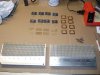
I used the insulators. See the pictures attached. The continuity tests were done with nothing attached to the transistors. Just bare leads... BCE. I will continue to test them with your recommendation, but would think you might want me to remove them from the heatsink first to eliminate the grounding issue.... no?

The Thermal paste was not silver based (arctic silver. Just standard thermal paste.) None of the paste was touching the leads. And none of the spring clips is near the pins... although not clear in the picture.
 

Attachments

  • Heatsink1.jpg
    Heatsink1.jpg
    31 KB · Views: 54
  • Heatsink2.jpg
    Heatsink2.jpg
    26 KB · Views: 43
  • Heatsink3.jpg
    Heatsink3.jpg
    37.2 KB · Views: 56
I used the insulators. See the pictures attached. The continuity tests were done with nothing attached to the transistors. Just bare leads... BCE. I will continue to test them with your recommendation, but would think you might want me to remove them from the heatsink first to eliminate the grounding issue.... no?

The Thermal paste was not silver based (arctic silver. Just standard thermal paste.) None of the paste was touching the leads. And none of the spring clips is near the pins... although not clear in the picture.


Now I'm perplexed, is there metal exposed on the back of the transistors, and is it capable of being touched by the mounting screws.

e b c, NONE should show any ohms to the heatsink when mounted and not connected to anything. c is the usual culprit.

Some transistors have an insulation buffer around the hole so the screw cannot short it out.
 
Well, I was a bonehead and made a mistake when measuring the continuity. There were wires touching ground on those pins. I rechecked them all, and there is NO continuity (shorts) to the heatsink on ANY of those transistors. I am checking the pinouts per your previous post and will be back to post all findings as soon as I get the readings. I know it is getting late there for you, but I will have the readings posted as soon as I get them. Maybe 15-20 minutes... It may take longer to post the results than to take the readings.
 
I'll be looking at them tomorrow.

It's getting late and this is the LAST post of the night. I may be back on from noon - 3 pm tomorrow, but then I have to go out for the rest of the night.
 
Back
Top Bottom