• The move to the new server is done. There are some software and database maintenance updates in process. This has us passing the hat around to help out. We appreciate any donations. Seriously, even a dollar helps. The payment page may be found here - https://www.audiokarma.org/support.html

SX 450 No AM/FM

What's the voltage on Pin 2, S3 2/2F? Should be 13.7vdc If you can contact the ROTARY piece that Pin 2 is supposed to contact, meter voltage on that in a free area. Should be same as pin 2. If not, Take a wooden splint (BBQ Match works) and press ever so slightly on Pin2 tab while metering the Rotary piece on the wafer. Somethings either DIRTY as hell or not making contact at the switch.
When you have voltage on the rotary wafer, check PIN3 IN AM, Pin 11 in FM.
S3 2/2 F pin 2 - 13.71 vdc. I'm confused on the rotary wafer for pin 2.

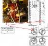
S3 2_2 switch 3.jpg
 
Each wafer has a front and a back side. Front side is toward the faceplate. Your picture is showing the back side of the wafer. With what looks like pin 5 circled. Go to the other side of the wafer and check that pin 2 is selected (it' will be on opposite side of vertical). Set the Selector on AM! Pin 2 and Pin 3 should now be connected. POWER OFF and Ohm Meter across the 2 pins. Should have 0.0 or close to it. Then turn the Selector to FM. Pins 2 and 11. Meter across pin 2 and 11. Same thing. An O/L reading on either or both means an open circuit and no voltage to pins 3 or 11 or both.

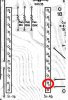
Presuming that your pic is showing pin 5 circled in RED, Then pin 2 is circled in Green.
450 wafer.jpg
 
Each wafer has a front and a back side. Front side is toward the faceplate. Your picture is showing the back side of the wafer. With what looks like pin 5 circled. Go to the other side of the wafer and check that pin 2 is selected (it' will be on opposite side of vertical). Set the Selector on AM! Pin 2 and Pin 3 should now be connected. POWER OFF and Ohm Meter across the 2 pins. Should have 0.0 or close to it. Then turn the Selector to FM. Pins 2 and 11. Meter across pin 2 and 11. Same thing. An O/L reading on either or both means an open circuit and no voltage to pins 3 or 11 or both.

Presuming that your pic is showing pin 5 circled in RED, Then pin 2 is circled in Green.
View attachment 2691702
1. Power off; Selector on AM - across Pin 2 and 3 - 27.5 ohm (moving around)
2. Power off; Selector on FM - across Pin 2 and 11 - OL

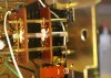
Here's where I touched the pins with my DMM set to ohms.

S3 2_2 F pins 2,3,11.jpg

Larry, Thanks for the clarification on wafer and pin positions. I was reading the placement of the pins in the wrong location. Looking at the schematic for proper location was confusing.
 
Last edited:
Cleaning of the switch is needed. If your skill level is not up to taking it apart (you'll need to desolder the switch boards from the main board, and disconnect the shaft from the front plate), the best you can hope for is to spray it with Deoxit D-5, wait 1/2 hour, give it a fresh spritz, then give it and your wrist a workout. 40-50 back and forth rotations, vigourously! The DeOxit will, (provided the contacts are solid) scrub the contaminants off the metal leaving a clean area for the contacts to work with. Cross your fingers, you may still have to disassemble the switch to physically clean it. But we need to work up to that.
 
Cleaning of the switch is needed. If your skill level is not up to taking it apart (you'll need to desolder the switch boards from the main board, and disconnect the shaft from the front plate), the best you can hope for is to spray it with Deoxit D-5, wait 1/2 hour, give it a fresh spritz, then give it and your wrist a workout. 40-50 back and forth rotations, vigourously! The DeOxit will, (provided the contacts are solid) scrub the contaminants off the metal leaving a clean area for the contacts to work with. Cross your fingers, you may still have to disassemble the switch to physically clean it. But we need to work up to that.
I have already removed everything including the tuner wheel to get access to the selector wafers a few days ago. I sprayed the front and back of both wafers with CRC-QD and D5 and worked them back and forth many times. Is the next step to desolder it from the PCB so I can get full access to cleaning the wafers?

IMGP0006.JPG
 
Last edited:
If you read pin 2 on the wafer itself and get 13.7V then you've established that the Switch rotor is getting power. Yeah, next step is to remove the switch, break it down and physically clean the copper elements. Be very careful of the arms as they will bend easily and usually can't be bent back without getting them lined up to contact wiper. Check to make sure the arm is actually making contact on the copper ring. No contact, no voltage to other pins.
 
If you read pin 2 on the wafer itself and get 13.7V then you've established that the Switch rotor is getting power. Yeah, next step is to remove the switch, break it down and physically clean the copper elements. Be very careful of the arms as they will bend easily and usually can't be bent back without getting them lined up to contact wiper. Check to make sure the arm is actually making contact on the copper ring. No contact, no voltage to other pins.
I will remove the selector switch from the PCB and clean pin 2 and 3 (all of them for that matter on both wafers). Once removed, I plan to use 600 grit sandpaper to lightly brush the copper contacts to get them clean.

Thanks Larry and Pio1980.
 
I will remove the selector switch from the PCB and clean pin 2 and 3 (all of them for that matter on both wafers). Once removed, I plan to use 600 grit sandpaper to lightly brush the copper contacts to get them clean.

Thanks Larry and Pio1980.
I pulled the selector switch off the PCB. There were a lot of layers that had to come off to get there. I sprayed all four sides of the two wafers with CRC-QD and wiped them off with a cotton swab. Next came D5 and wiped off with a cotton swab. I worked the selector back and forth about 40 times.

I used a 4 power loupe and watched each copper riveted pin (all of them) flex up as I rotated the selector switch copper ring to insure good contact. I did bent down S3 2/2 F Pin 3 and it now flexes up when the rotor is turned. I did not use any sandpaper between the contacts.

Since I have this switch out, should I perform any other tests? Continuity?


selector switch removed.jpg
 
Last edited:
I pulled the selector switch off the PCB. There were a lot of layers that had to come off to get there. I sprayed all four sides of the two wafers with CRC-QD and wiped them off with a cotton swab. Next came D5 and wiped off with a cotton swab. I worked the selector back and forth about 40 times.

I used a 4 power loupe and watched each copper riveted pin (all of them) flex up as I rotated the selector switch copper ring to insure good contact. I did bend down S3 2/2 F Pin 3 and it now flexes up when the rotor is turned. I did not use any sandpaper between the contacts.

Since I have this switch out, should I perform any other tests? Continuity?


View attachment 2693016

Continuity yes, absolutely. That's why you are there.
 
Continuity yes, absolutely. That's why you are there.
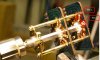
I tested for continuity for S3 2/2 F pin 2. I connected one end of the DMM to the base of the PCB for pin 2 and the other to the copper ring as shown. I got continuity for all four selector positions (AM, FM, Phono, AUX). Seems like I should be getting the 13.7 vdc for all four positions now.

selector switch pin 2 continuity.jpg
 
I tested for continuity for S3 2/2 F pin 2. I connected one end of the DMM to the base of the PCB for pin 2 and the other to the copper ring as shown. I got continuity for all four selector positions (AM, FM, Phono, AUX). Seems like I should be getting the 13.7 vdc for all four positions now.

View attachment 2693188
Hopefully, double check with care before proceeding.
 
Back
Top Bottom