• The move to the new server is done. There are some software and database maintenance updates in process. This has us passing the hat around to help out. We appreciate any donations. Seriously, even a dollar helps. The payment page may be found here - https://www.audiokarma.org/support.html

SX-535 Bright DB

SG19

AK Subscriber
Subscriber
This is my 1st attempt at a real electrical issue on a piece of stereo equipment , limited to a meter and a DBT for test equipment at this point.

The symptoms , lights burnt out and vary low volume even at 12 or 1:00 , both channels all inputs ,all switch positions ,both speakers A and B , sometimes meter lights and dial needle light will light , sometimes not ?

Was checking DC offset and wasn't getting much of a reading so I did some basic voltage checks and wasn't finding much.

Decided to check fuses and found both F7 & F8 open, thought easy enough replaced the fuses and put it on the DB ...

Bulb stays bright unless I remove both fuses. F7 & F8 are in line with the transformer 3 diodes and 2 stabilizers , the schematic I have is too blurry to make out values.

I'm not vary experienced at troubleshooting components and it's even more difficult when I can't make out the details , I'm assuming I have a shorted component , trying to breakdown these stabilizers with the blurry / blobby schematic and my old eyes is kind of a challenge , if anyone has a sharper copy of the service manual and or an idea where I need to check next it would be much appreciated.

Thank you
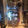
1789616591399.jpeg


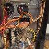
1789617002121.jpeg

1789617042909.jpeg

1789617083173.jpeg
 
  • Like
Reactions: mbz
Register to hide this ad
Try the sm from electrotanya

Blowing fuses F7, F8 means a problem downstream of those fuses, ie, Left or Right power amp stage, driver and output transistors and... A good first step is to identify the faulty channel then test components within that channel.

Taking a punt, measure dc voltage at left power amp pin TP1, black meter probe connected to any black speaker connector. Expecting about +/-10mV at TP1. Repeat measurement on right channel at pin TP2, again, +/-10mV.

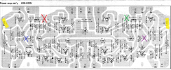
Also try measuring DC voltages at the following points
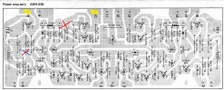
D3 anode, (marked in Green) +1.2Vdc
D4 anode (Red) +1.2Vdc
VR1 wiper (middle leg, Purple) -1.2Vdc
VR2 wiper (Blue) -1.2Vdc
 

Attachments

  • SX535.png
    SX535.png
    380.3 KB · Views: 7
Try the sm from electrotanya

Blowing fuses F7, F8 means a problem downstream of those fuses, ie, Left or Right power amp stage, driver and output transistors and... A good first step is to identify the faulty channel then test components within that channel.

Taking a punt, measure dc voltage at left power amp pin TP1, black meter probe connected to any black speaker connector. Expecting about +/-10mV at TP1. Repeat measurement on right channel at pin TP2, again, +/-10mV.

Also try measuring DC voltages at the following points
D3 anode, (marked in Green) +1.2Vdc
D4 anode (Red) +1.2Vdc
VR1 wiper (middle leg, Purple) -1.2Vdc
VR2 wiper (Blue) -1.2Vdc
TP-1 + 3.7vdc

TP-2 OL

D3 +1 vdc

D4 +1.75 vdc

VR1 +0.97 vdc

VR2 +0.97 vdc


Also thanks for the SM link :thumbsup:
 
  • Like
Reactions: mbz
Looks like multiple issues,
TP-1 + 3.7vdc
TP-1 is close enough to dc offset, this will trigger protection.
Sort out the right channel first

Right channel offset, expect > 20Vdc. probably near rails, remeasure
Diode test right channel Q8,10,12,14, see below

D3 +1 vdc
VR1 +0.97 vdc
No volt drop /current flow? through D3, D5, VR1
Measure Q5 b/c/e voltages to GND

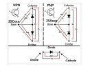
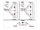
Nice graphic from markthefixer on diode testing,
 

Attachments

  • DiodeTest.JPG
    DiodeTest.JPG
    40.8 KB · Views: 3
Measuring grd probe blk speaker grd , all fuses set , on DB tester

TP-1 200m range 3.7 ish , jumping around alot

TP-2 2volt range 0.92vdc
 
  • Like
Reactions: mbz
Need to go to day job for a few hours hopefully others will chime in

Ignore comments about tripping protection, amp does not have a relay based protection circuit.

High TP2 voltage indicates problem with right channel

Q5 20 v range , grd blk speaker term

B -3.09 vdc

C -0.98vdc

E -3.68 vdc
Q5c is in the ballpark.
Q5 Vbe looks OK (0.6V)
Q5 Vb and Ve both much lower than expected -30Vdc abouts
 
Need to go to day job for a few hours hopefully others will chime in

Ignore comments about tripping protection, amp does not have a relay based protection circuit.

High TP2 voltage indicates problem with right channel


Q5c is in the ballpark.
Q5 Vbe looks OK (0.6V)
Q5 Vb and Ve both much lower than expected -30Vdc abouts
I appreciate your help , thank you
 
I needed a reset, working on other threads led to some confusion my part.

Fault
Bright DBT, F7, F8 fuses for +/-B1(+/-27V) power amp rails previously blown, problem downstream F7, F8.
Some voltages
TP-1(L) 3.7mV
TP-2(R) 0.92V
Q5b -3.09V
Q5c -0.98V
Q5e -3.68V
Q8b 1.75V

High TP-2 voltage suggests problem is with right channel

Would be great to confirm 100% problem is with right channel and not left ch or power supply.

If you have suitable desoldering skill you could unsolder the right power amp pins 8 & 10.
Do not unwrap the wire from the posts. Take care not to allow the posts to short on anything.
Then DBT power up, expect dim DBT.

If unsoldering posts is too difficult then alternative is to perform voltage measurements
Please measure Vdc at,
Pin 8
Pin 10
R22 (red)
R24 (blue)
 

Attachments

  • SX535amp_2.jpg
    SX535amp_2.jpg
    136 KB · Views: 2
Voltage checks done , did not desolder pins , if it's absolutely necessary I can I just got what you ment , de-solder and pull the pins from the board but leave them wire wrapped.

Pin8 -1.4 vdc

Pin 10 +1.5 vdc

R22 + 1.24 vdc

R24 - 60 vdc
 
  • Like
Reactions: mbz
What wattage bulb are you using for DBT, minimum 75W? 100W should be ok
Is the bulb very bright.

Pins 8 and 10 should be the +/-27V power supply to the right channel, only seeing 1.4/1.5V???
R24 - 60 vdc
"must" be a measurement error, plz recheck
 
What wattage bulb are you using for DBT, minimum 75W? 100W should be ok
Is the bulb very bright.

Pins 8 and 10 should be the +/-27V power supply to the right channel, only seeing 1.4/1.5V???

"must" be a measurement error, plz recheck

Re-check R24 -0.62 vdc must of wrote it down wrong , it was getting late.

I believe the bulb I'm using is a 60W , it's a clear globe style bulb , only incandescent I had around , 100w clear bulbs are on my Amazon list just haven't , harder to come by than you would think , everything is LED now.
 
  • Like
Reactions: mbz
The 60W bulb might be starving the amp of power however its only a 20W amp... Wouldn't expect +/-B1 to crash because of the 60W...

Have you diode tested Q8,10,12,14???
Try incircuit first since looking for a short.
Nice graphic from markthefixer below.
Set mm to diode function, red/black indicate probe orientation, need to test 6 combinations, 2 results expected, either 640mV (500-750mV?) or OL (open)

Failing that, time for some fishing...
With amp powered off/unplugged
Pull F7, F8
Measure resistance between right power amp pin 8 and GND
Repeat for pin 10 and GND
Reinsert F7, F8
DBT power up

measure voltage drop across
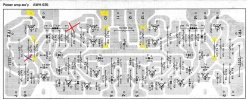
R26, ie one meter probe connected to one side of R26, other probe connected to other, see yellow crosses below, meter set to 2Vdc scale
Repeat for R28
Repeat for R25
Repeat for R27

Problem could be with output transistors Q12, Q14 or the driver transistors Q8, Q10. By measuring the volt drop across R26,,, you can calculate the current flow then compare with other channel.

If currents are all about the same then suspect outputs, unsolder Q12, Q14 and try diode test of each. If you have some diodes at hand eg 1N4148 1N400x,,, then solder diodes to the base and emitter pads.
Q12 diode anode to Q12b, cathode to Q12e
Q14 diode anode to Q14e, cathode to Q14b

the diodes replicate the transister b-e junction
then dbt power up
 

Attachments

  • DiodeTest.JPG
    DiodeTest.JPG
    40.8 KB · Views: 3
  • SX535amp_2.jpg
    SX535amp_2.jpg
    136.8 KB · Views: 2
Last edited:
I may have to come back late tonight or tomorrow have a few things going on tonight .

I did find something possibly

Diode test : Q10

Base R to E blk OL
Base Blk to E R .62

Base R to C Blk OL
Base Blk to C R .50

C R to E Blk .22
C Blk to E R .25

I did a 6 point check on Q14 as well and got readings at all 6 points , Q 10 seems to be open R base to blk emitter or collector .

I appreciate your help I will be back here tomorrow ,

Thank you
 
  • Like
Reactions: mbz
Ok , I don't have any diodes so I wasn't able to do the last test

Q10 , see above

Q14
base R to E blk .24
base blk to E R .21

base R to C blk .24
base blk to C R .21

Coll R to E Blk .030
Coll Blk to E R .031

Q12
Base R to E blk .32
Base blk to E R .27

Base R to C blk .57
Base blk to C R 1.11

Coll R to E Blk 1.09
Coll Blk to E R .49

Q8
Base R to E blk .69
Base blk to E R .75

Base R to C blk .68
Base blk to C R 1.1

C R to E blk 1.1
C blk to E R .56


fuses out , power unplugged

Pin 8 to grd open Pin 10 to grd open

Power on through DB

R25 -.152vdc

R26 -.152vdc

R27 +.152vdc

R28 +.150vdc
 
  • Like
Reactions: mbz
First up, in circuit testing is a little tricky. While you want to test a component, what you are doing is testing between 2 points in the circuit with the tester current "free" to select any low resistance (alternate) path. In circuit testing has the advantage of being quick and should give results when a short is expected.

Diode test : Q10

Base R to E blk OL... PNP so OK
Base Blk to E R .62... OK

Base R to C Blk OL...OK
Base Blk to C R .50... a little low but not short

C R to E Blk .22... Expect OL
C Blk to E R .25... Expect OL
C-E test possible alternate path from Q10c-R28-Q14cb-Q10e, ie suspect Q14????

Q14
base R to E blk .24...OL expected but alternate path R24, R32
base blk to E R .21... 0.6V expected but again low resistance path R24, R32

base R to C blk .24... OL, faulty Q10c-e?
base blk to C R .21... 0.6V, again, low resistance path through Q10c-e??

Coll R to E Blk .030... OL Possible path from Q14e-R32-R24-faulty Q10c-e-R28--Q14c
Coll Blk to E R .031

Q12
Base R to E blk .32... low resistance path R22-R30
Base blk to E R .27... low resistance path R22-R30

Base R to C blk .57...ok
Base blk to C R 1.11... same as Q8c-e

Coll R to E Blk 1.09... same as Q8c-e
Coll Blk to E R .49... possible R32-R22-Q12b-c

Q8
Base R to E blk .69...ok
Base blk to E R .75...OL ????

Base R to C blk .68...ok
Base blk to C R 1.1...OL, difficult to see alternate path

C R to E blk 1.1...OL, difficult to see alternate path
C blk to E R .56... OL, alternate path through Q12c-b

fuses out , power unplugged

Pin 8 to grd open Pin 10 to grd open
good

Power on through DB

R25 -.152vdc

R26 -.152vdc

R27 +.152vdc

R28 +.150vdc
All voltages the same so no abnormal current flow, only 27mA/0.004W
Problem with output transistors

Suggest pull output transistors Q12, Q14, repeat diode test out of circuit but note these are "beefy" items typically seeing Vce=50Vdc and Ic=amps so you component tester may pass them, your tester runs at Vce of a few volts and Ic=xxmA.

If output pass diode test then try and find some 1N4148 or some 1N400x diodes
 
I understand about trying to measure components in circuit , do you feel we have narrowed it down to the out put transistors at this point ?

Should I maybe just order a set of out put transistors , I was planning to order a rebuild kit for this receiver as well ?
 
Should I maybe just order a set of out put transistors
You could, these are the more expensive transistors so was trying to avoid it until certain.

do you feel we have narrowed it down to the out put transistors at this point ?
Balanced/equal current through those resistors make drivers unlikely. I'd say 80% outputs, 20% power supply.

You could try simply pulling Q12, Q14 then briefly DBT power up and confirm bulb is dim.
 
You could, these are the more expensive transistors so was trying to avoid it until certain.


Balanced/equal current through those resistors make drivers unlikely. I'd say 80% outputs, 20% power supply.

You could try simply pulling Q12, Q14 then briefly DBT power up and confirm bulb is dim.
That sounds like a good idea.

Another observation I made is I have no dial lights when the fuses are installed on DB, I do when I remove them , does that seem to be expected ? Sometimes the tuning meters & dial indicator light , sometimes they don't. My other SX-535 acted the same until I put the LED's in.

I have the set of replacement LED's since some were burnt out anyway , think I'll put them just for S & G since I'm going to eventually anyway.
 
Back
Top Bottom